Hyper-V Replica. This new Windows Server 2012 feature enables you to replicate a virtual machine to another host or into the cloud, instead of moving the virtual machine, and to synchronize all virtual machine changes from the primary host to the host that holds the replica.
In some cases, you might want to have a spare copy of one virtual machine that you can run if the original virtual machine fails. By implementing high availability, you have one instance of a virtual machine. High availability does not prevent corruption of software that is running inside the virtual machine. One way to address the issue of corruption is to manually copy the virtual machine periodically. You also can back up the virtual machine and its storage. Although this solution achieves the desired result, it is resource intensive and time consuming. In addition, because
backups are performed periodically, you never have the exact same copy as the running virtual machine.
To complete this simple demo, make sure that you meet the requirement in your Test Lab Environment.
Make sure that you have 2 Physical machine to complete this simple demo, which is Host1 & Host2.
In Host1, verify that you have Domain Controller Server (in my setup, i have domain Server in Hyper-V Host1.)
Verify also all Physical Host connected & join domain to DC1 server.
1 – On the Host1 machine, open Hyper-V Manager, right click Host1 and click Hyper-V Settings…

2 – In Hyper-V Settings, click Replication Configuration, then click Enable this computer as a Replica server…
** In the Authentication and ports section, select Use Kerberos (HTTP).
** In the Authorization and storage section, point to E:\OSI-VM-Replica\ folder then click OK….

3 – In the Settings interface, click OK…

4 – Next, open Windows Firewall and Enable Rule for Hyper-V Replica HTTP Listener (TCP-In)…

5 – Repeat steps 1 through 4 on Host2 Machine…
6 – On the Host1 Machine, in the Hyper-V Manager, right-click OSI-Svr-Core VM and then click Enable Replication, then click Next…

7 – On the Specify Replica Server interface, browse to OSI-Host2 machine then click OK…

8 – On the Specify Replica Server interface, click next…

9 – On the Specify Connection Parameters interface, review the settings, and ensure that Use Kerberos authentication (HTTP) is selected, and then click Next…

10 – On the Choose Replication VHDs interface, ensure that VM is selected, and then click Next…

11 – On the Configure Replication Frequency interface, select 30 seconds from drop-down list box, and then click Next…

12 – On the Configure Additional Recovery Points interface, select Maintain only the latest recovery point, and then click Next…

13 – On the Choose Initial Replication Method interface, click Send initial copy over the network, select Start replication immediately, and then click Next…

14 – On the Completing the Enable Replication Wizard interface, click Finish…

15 – Wait few minutes for the replication to finish…
** You can monitor the progress of the initial replication in the Status column in the Hyper-V Manager console…

16 – To validate the replication, right-click VM, select Replication, and then click View Replication Health…

17 – Review content of the interface that appears, and verify that there are no errors…

That’s all for now..
As at this point, i have completed my MCSA 2012 R2 certification step by step…
Active Directory Federation Services (AD S) in the Windows Server 2012 R2 OS provides flexibility for organizations that want to enable their users to log on to applications that are located on a local network, at a partner company, or in an online service.
With ADFS, your company can manage its own user accounts, and users only have to remember one set of credentials.
However, those credentials can provide access to a variety of applications, which typically are located in different locations.
ADFS is compliant with common Web services standards, thus enabling interoperability with identity federation solutions that other vendors provide.
AD FS addresses a variety of business scenarios where the typical authentication mechanisms used in an organization do not work.
More info & reading : http://technet.microsoft.com/en-us/windowsserver/dd448613.aspx
For this basic ADFS demo, i’m using my previous VM which is my domain controller (DC1), member server (SVR1) and 1 windows 8.1 client PC…
1st – Create a DNS record for AD FS
1 – On Domain controller (DC1) server, open DNS console and add new host…
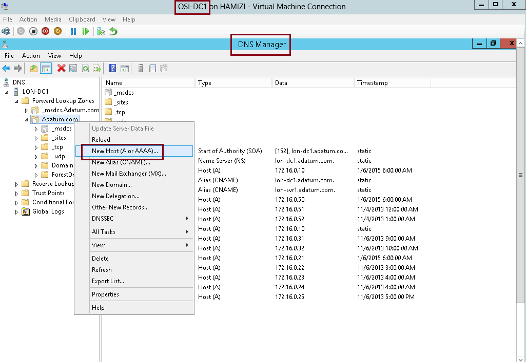
2 – In the New Host box, type adfs, in the IP address box, type 172.16.0.10, and then click Add Host…
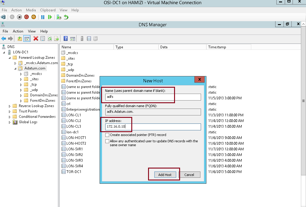
3 – Then click OK…

** before we proceed, make sure you create a new AD user called adfsService…
2nd – Install AD FS
1 – Still on the DC1 domain server, open server manager, click Add Roles and Features, proceed the step until you get Select server roles interface, and then click Active Directory Federation Services, then proceed with next…

2 – On the Select features interface, click Next…
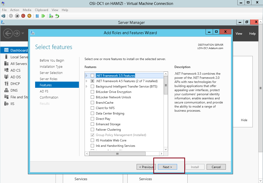
3 – On the Active Directory Federation Services (AD FS) interface, click Next…

4 – then click Install…

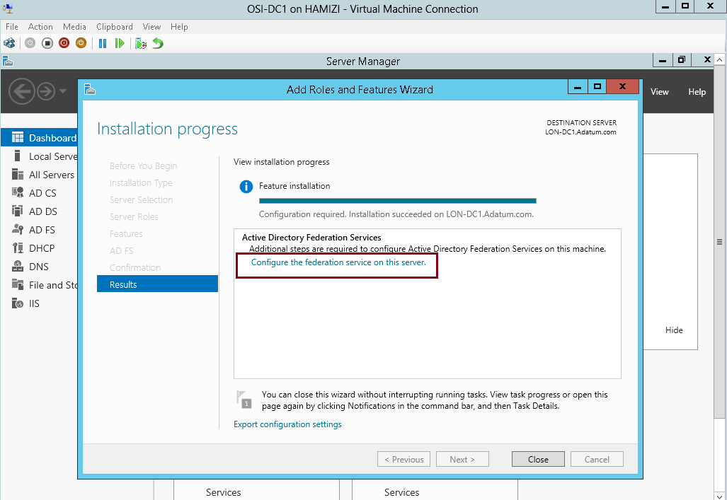
5 – Once the installation completed, click Configure the federation service on this server…
3rd – Configure AD FS
1 – on the Welcome interface, click Create the first federation server in a federation server farm, and then click Next…

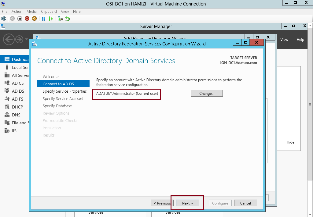
2 – On the Connect to Active Directory Domain Services interface, proceed with Next…
3 – On the Specify Service Properties interface, in the SSL Certificate box, select adfs.adatum.com…
** In the Federation Service Display box, type Adatum Organization, and then click Next…

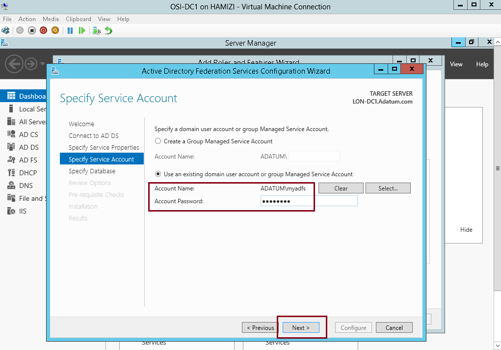
4 – On the Specify Service Account interface, click Use an existing domain user account or group Managed Service Account and then choose adfs user that you created previously, and then click next…
5 – On the Specify Configuration Database interface, click Create a database on this server using Windows Internal Database, and then click Next…

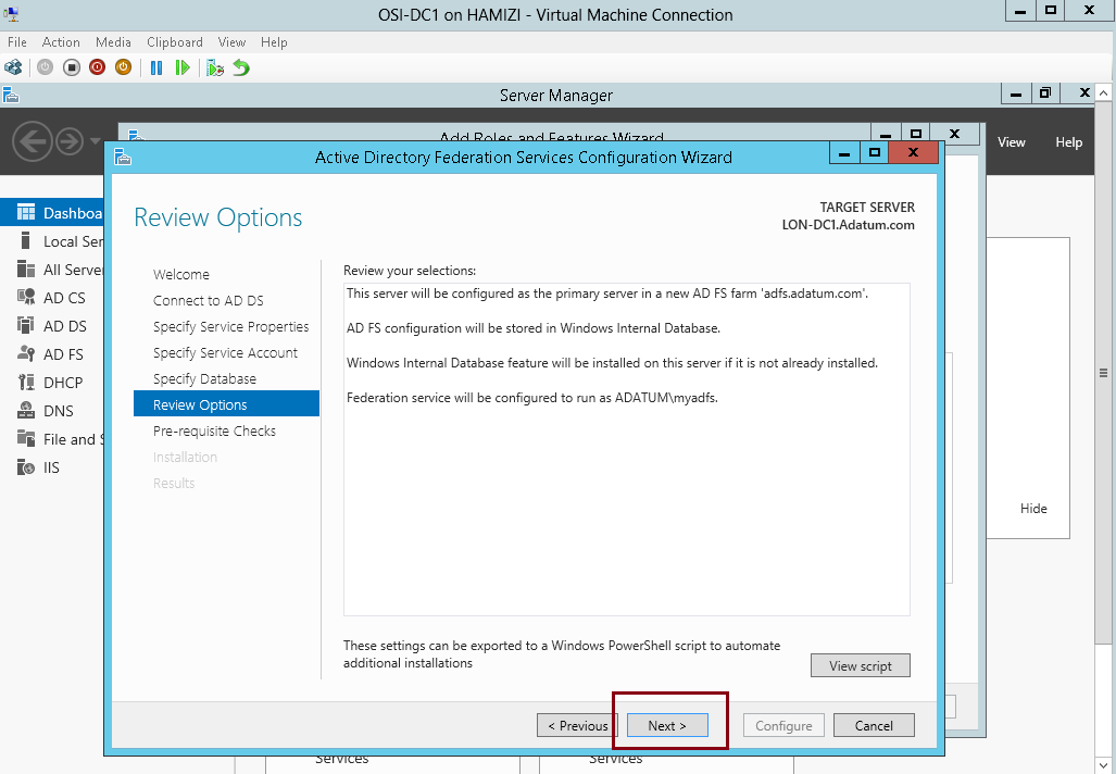
6 – On the Review Options interface, click Next…
7 – On the Pre-requisite Checks interface, verify that all prerequisite passed and then click Configure…

8 – On the Results interface, click Close…
** Please take note that adfs.adatum.com certificate was preconfigured for this task. In your own environment, you need to obtain this certificate.

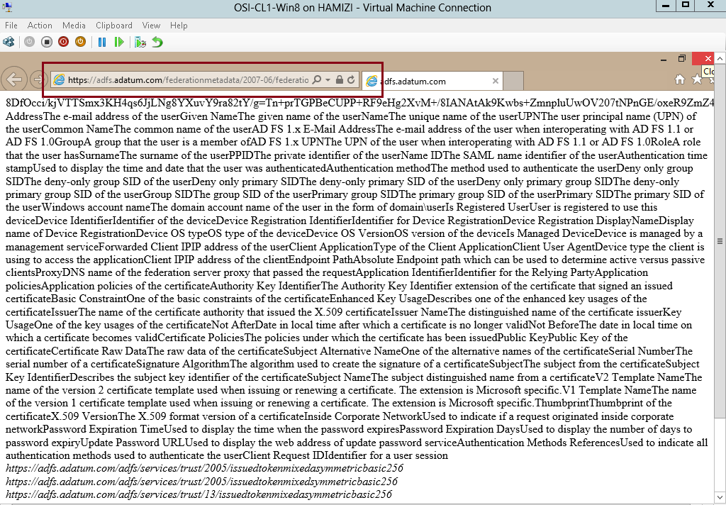
9 – to verify the ADFS functionality, log in to Windows 8.1 client PC as a AD user, and the open IE and type : https://adfs.adatum.com/federationmetadata/2007-06/federationmetadata.xml, and then verify that the file loads successfully…
4th – Configure a certificate for the application
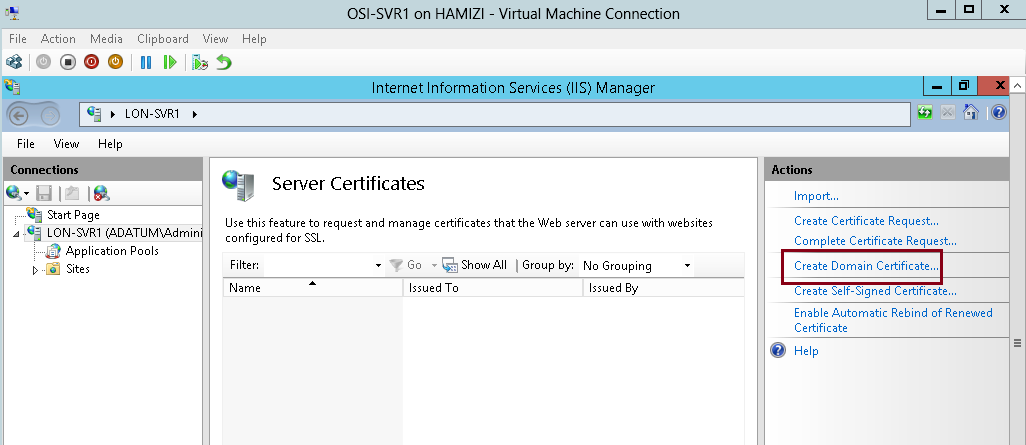
1 – Now switch to SVR1 server and open Internet Information Services (IIS) Manager and then open Server
Certificates…

2 – then click Create Domain Certificate…
3 – In the Create Certificate interface on the Distinguished Name Properties, enter the following information (please refer to snapshot), and then click Next…

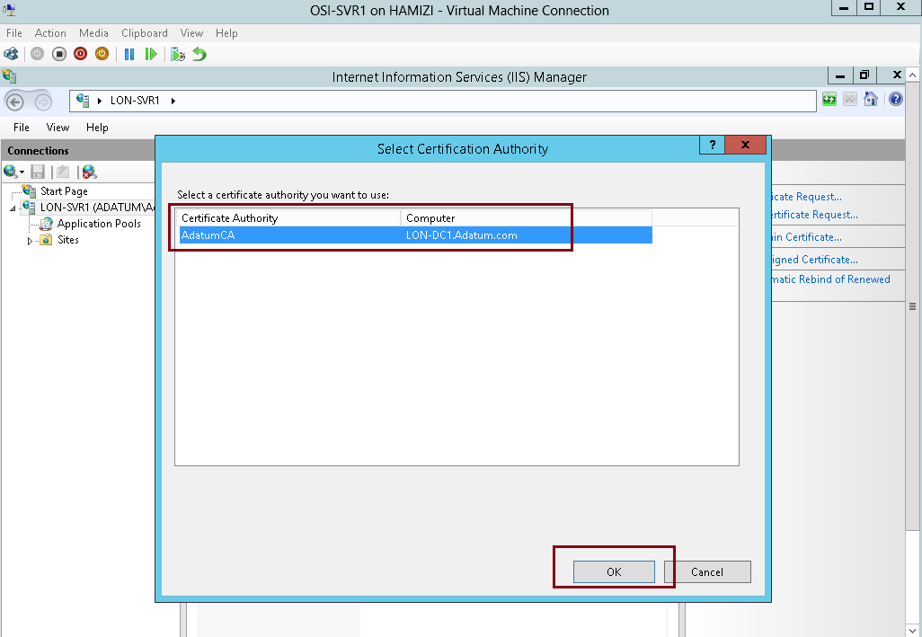
4 – On the Online Certification Authority interface, click Select…

5 – click AdatumCA, and then click OK…
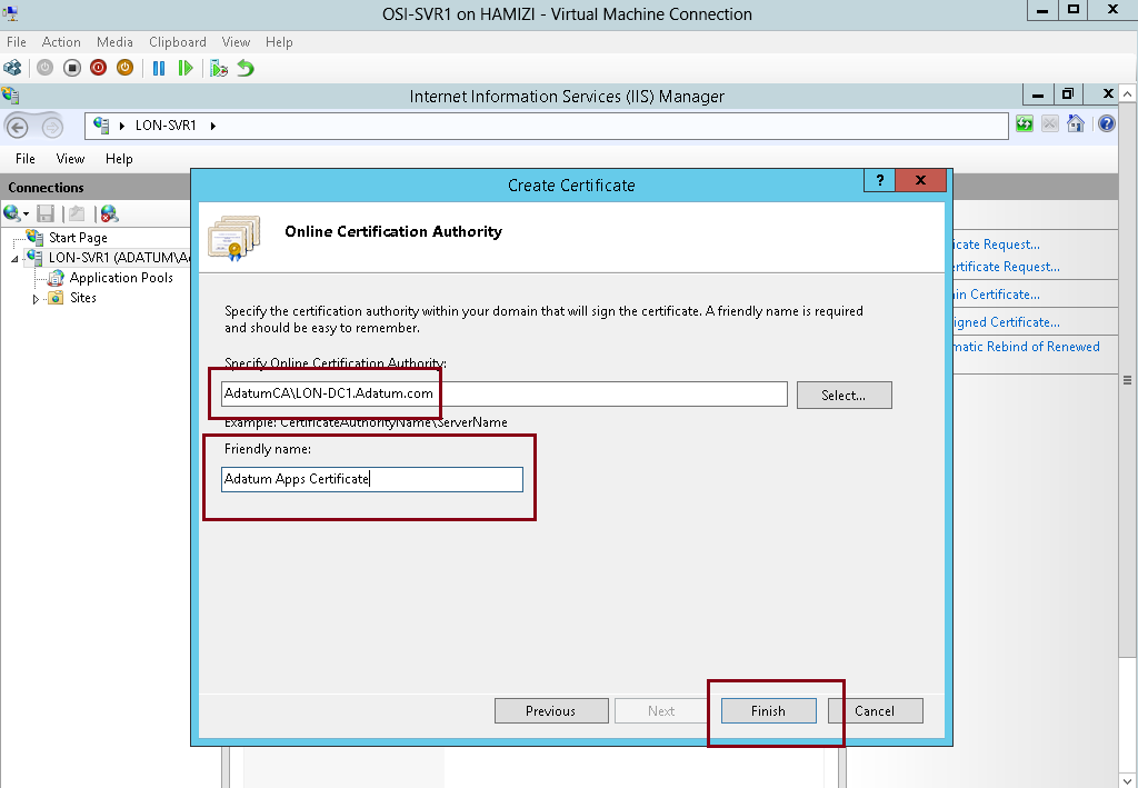
6 – On the Online Certification Authority interface, in the Friendly name box, type Adatum Apps Certificate, and then click Finish…
7 – In IIS Manager, expand Sites, click Default Web Site, and then click Bindings…

8 – In the Site Bindings interface, click Add…

9 – In the Add Site Binding interface, in the Type box, select https, then in the SSL certificate box, select Adatum Apps Certificate, and then click OK…

5th – Configure the Active Directory claims-provider trust
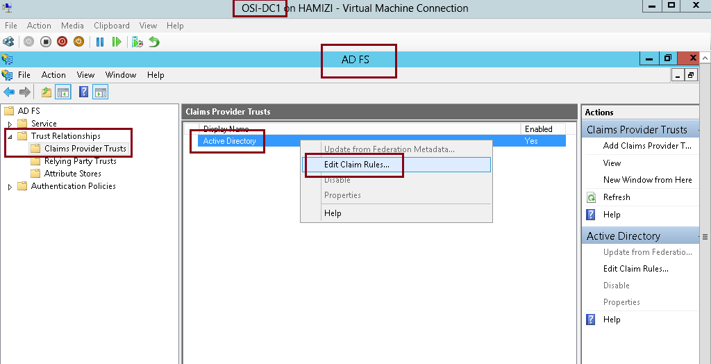
1 – Switch to DC1 server, and open AD FS Management, expand Trust Relationships, and then click Claims Provider
Trusts, in the middle pane, right-click Active Directory, and then click Edit Claim Rules…
2 – In the Edit Claims Rules for Active Directory interface, on the Acceptance Transform Rules tab, click Add Rule…
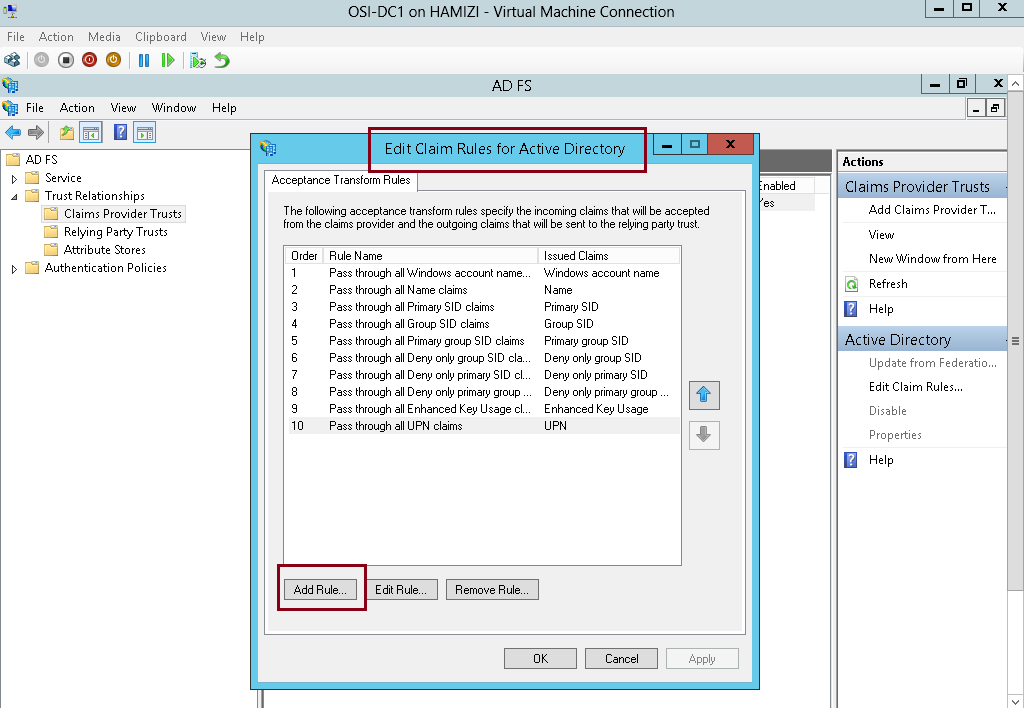
3 – In the Claim rule template box, select Send LDAP Attributes as Claims, and then click Next…

4 – On the Configure Rule interface, in the Claim rule name box, type Outbound LDAP Rule, then in the Attribute Store drop-down list, select Active Directory.
** In the Mapping of LDAP attributes to outgoing claim types section, select the following values and then click Finish:
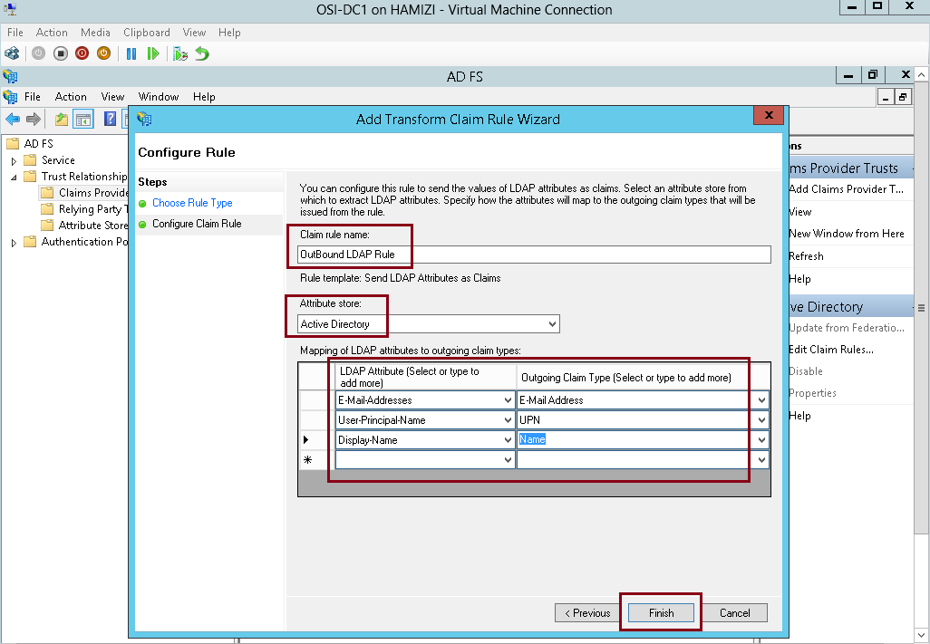
5 – Then click OK…

6th – Configure the application to trust incoming claims
1 -Switch to SVR1 server, and then open Windows Identity Foundation Federation Utility console….
2 – On the Welcome to the Federation Utility Wizard interface, in the Application configuration location box, type C:\inetpub\wwwroot\AdatumTestApp\web.config for the location of the sample web.config file…
** In the Application URI box, type https://lon-svr1.adatum.com/AdatumTestApp/ to indicate the path to the sample application that will trust the incoming claims from the federation server, and then click Next to continue…

3 – On the Security Token Service page, click Use an existing STS, in the STS WS-Federation metadata document location box, type https://adfs.adatum.com/federationmetadata/2007-06/federationmetadata.xml, and then click Next to continue…

4 – On the STS signing certificate chain validation error interface, click Disable certificate chain validation, and then click Next…

5 – On the Security token encryption interface, click No encryption, and then click Next…

6 – On the Offered claims interface, click Next…
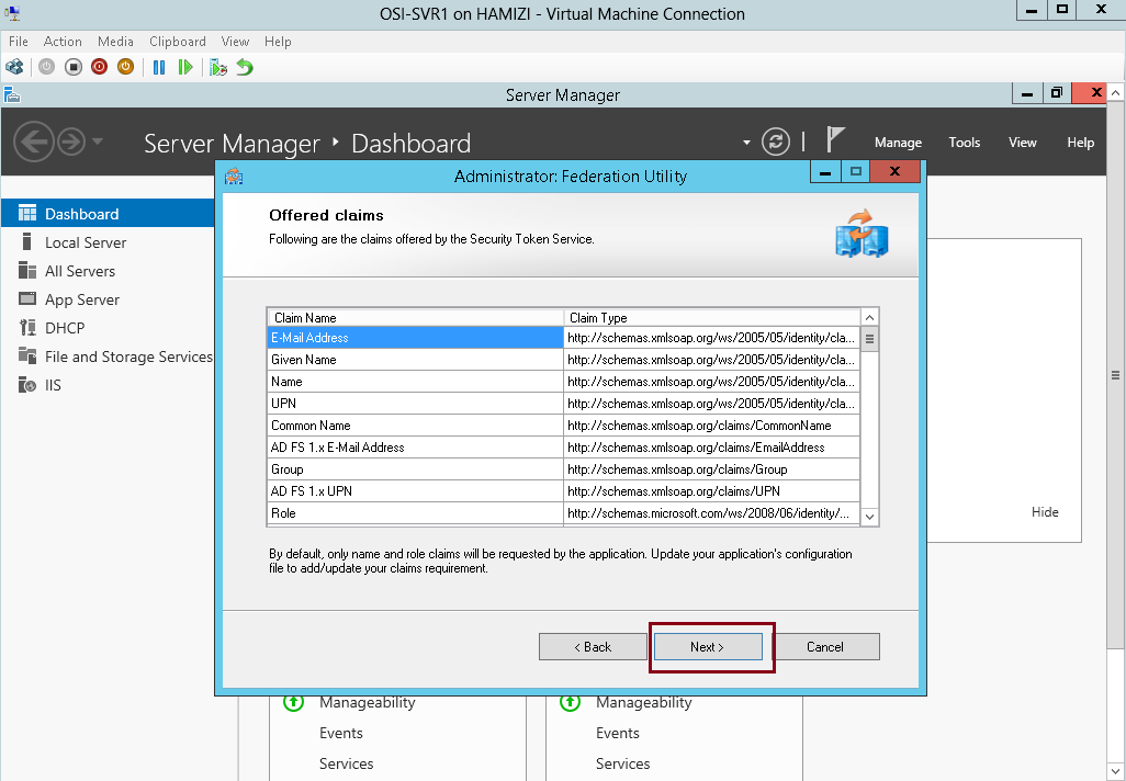
7 – and then click Finish and OK…

7th – Configure a relying-party trust for the claims-aware application
1 – Now switch to DC1 domain server, in the ADFS console, right-click Relying Party Trusts, and then click Add Relying Party Trust…

2 – on the Welcome interface, click Start…

3 – On the Select Data Source interface, click Import data about the relying party published online or on a local network…
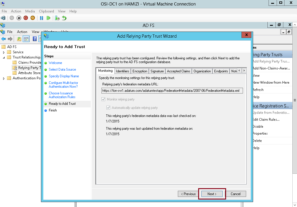
** In the Federation Metadata address (host name or URL) box, type https://lonsvr1.adatum.com/adatumtestapp/, and then click Next. This downloads the metadata configured in the previous task…
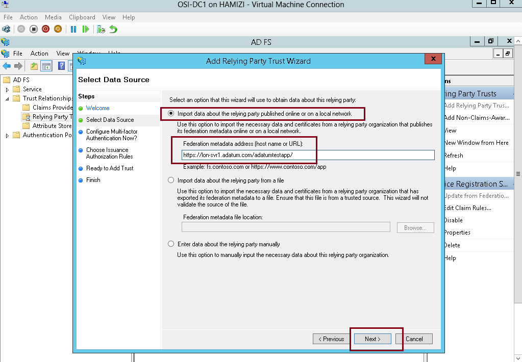
4 – Next in the Display name box, type Adatum Test Apps, and then click Next…
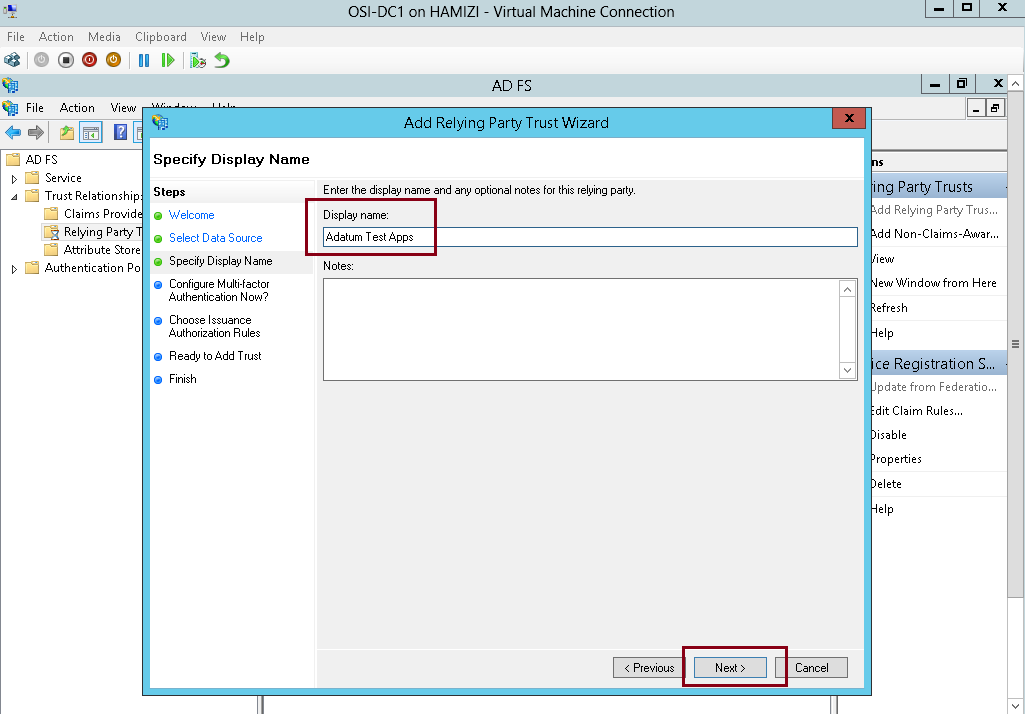
5 – On the Configure Multi-factor Authentication Now interface, click I do not want to configure multifactor
authentication settings for this relying party trust at this time, and then click Next…

6 – On the Choose Issuance Authorization Rules interface, click Permit all users to access this relying party, and then click Next…

7 – On the Ready to Add Trust interface, click Next…
8 – On the Finish interface, click Close…

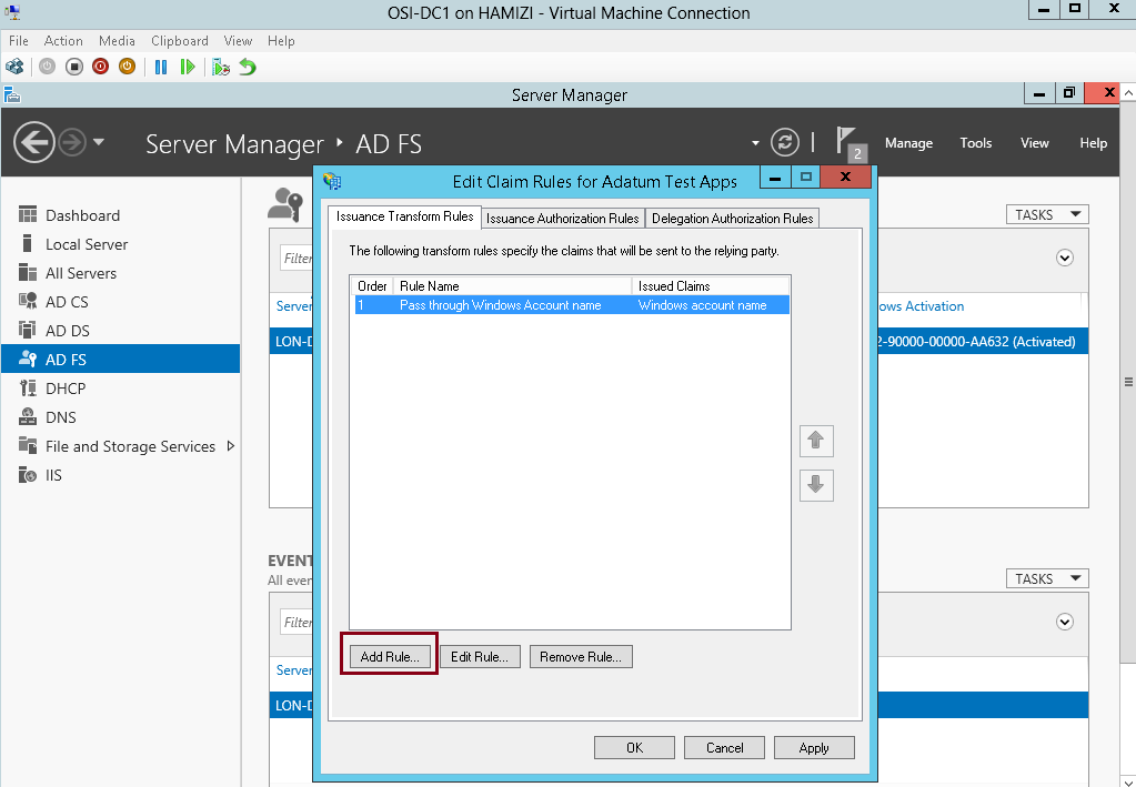
8th – Configure claim rules for the relying-party trust
1 – still in DC1 domain server, in the Edit Claim Rules for Adatum Test Apps interface, on the Issuance Transform Rules tab, click Add Rule…

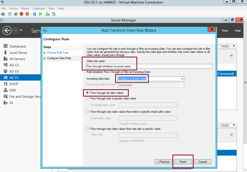
2 – In the Claim rule template box, select Pass Through or Filter an Incoming Claim, and then click Next…

3 – In the Claim rule name box, type Pass through Windows account name…
** In the Incoming claim type drop-down list, click Windows account name, and then click Finish…
4 – On the Issuance Transform Rules tab, click Add Rule…
5 – In the Claim rule template box, select Pass Through or Filter an Incoming Claim, and then click Next…
6 – In the Claim rule name box, type Pass through E-Mail Address…
** In the Incoming claim type drop-down list, click E-Mail Address, and then click Finish…

7 – On the Issuance Transform Rules tab, click Add Rule…

8 – In the Claim rule template box, select Pass Through or Filter an Incoming Claim, and then click Next…

9 – In the Claim rule name box, type Pass through UPN…
** In the Incoming claim type drop-down list, click UPN, and then click Finish…

10 – On the Issuance Transform Rules tab, click Add Rule…
11 – In the Claim rule template box, select Pass Through or Filter an Incoming Claim, and then click Next…

12 – In the Claim rule name box, type Pass through Name…
** In the Incoming claim type drop-down list, click Name, and then click Finish…
13 – Then click OK…

14 – Now switch to Windows 8.1 Client PC, log in as domain user and then open IE, then type https://lon- svr1.adatum.com/AdatumTestApp/…
** Notice that Windows Security window will pop out, then sign in as domain user…

15 – verify that the claim information is displays….

9th – Configure IE to pass local credentials to the application automatically
1 – Still in Windows 8.1 client PC IE, then open Internet Options…
** In the Internet Options Properties interface, click Security tab, click Local intranet, and then click Sites…
2 – In the Local intranet interface, click Advanced…
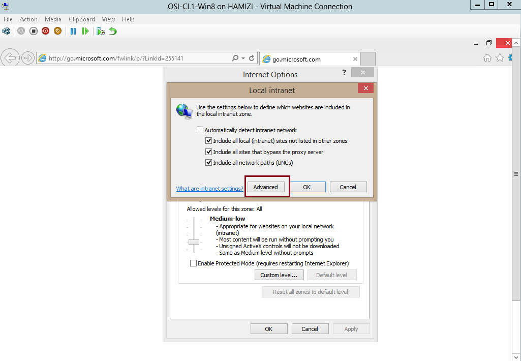
3 – In the Local intranet interface, in the Add this website to the zone box, insert https://adfs.adatum.com and https://lon-svr1.adatum.com, and then click Close, and click OK twice…

4 – Then in the IE, type https://lon-svr1.adatum.com/AdatumTestApp/, notice that you were not prompted for credentials…
That’s all for now, we have successfully installed and configured ADFS, and verified that it is functioning by
viewing the FederationMetaData.xml file contents. We also have successfully configured ADFS to support authentication for an application…
In my post this time, lets go through a simple step on how you as a Server Admin can implementing ADDS Sites and Replication in Windows Server 2012 R2.
In ADDS infrastructure, standard domain controllers replicate AD Directory information by using a multimaster replication model.
This means that if a change is made on one domain controller, that change then replicates to all other domain controllers in the domain, and potentially to all domain controllers throughout the entire forest.
More information, please log in to : http://technet.microsoft.com/en-us/library/cc775549%28v=ws.10%29.aspx
For this demo, i will assume that we have this kind of scenario so that with this demo, you can understand whats going on within the steps.
“Your organization has deployed a single ADDS domain, with all the domain controllers located in the JakartaHQ data center.
As the organization has grown and added branch offices with large numbers of users, it has become apparent that the current ADDS environment does not meet the company requirements.
Users in some branch offices report that it can take a long time for them to sign in on their computers.
Access to network resources such as the company’s Microsoft Exchange 2013 servers can be slow, and they fail sporadically.
As one of the senior network administrators, you are responsible for planning and implementing an ADDS infrastructure that will help address the business requirements for the organization.
You are responsible for configuring AD DS sites and replication to optimize the user experience and network utilization within the organization.”
What i have for this demo :
1 – 1 Domain Server (DC1)
2 – 1 Member Server (this server will be upgraded to Domain Controller)
1st – Install domain controller in member server
2nd – Rename the default site
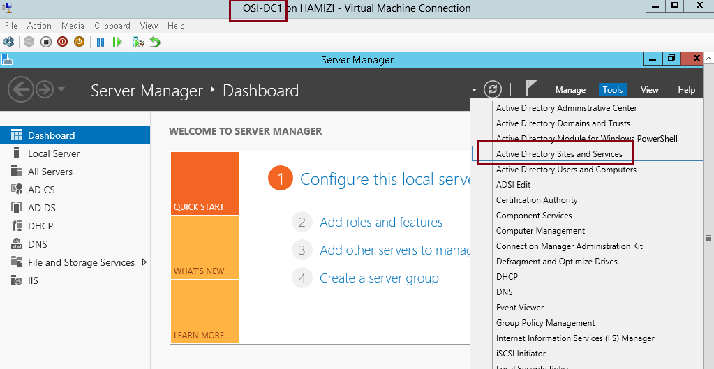
1- Log in to DC01 domain server and open Active Directory Sites and Services…
2 – Next, In Active Directory Sites and Services console, right-click Default-First-Site-Name, and then click Rename…
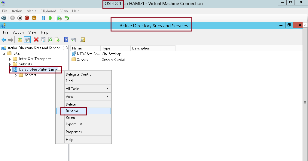
3 – I rename the Default-First-Site-Name to JakartaHQ, and then verify that both LON-DC1 and TOR-DC1
belong to the JakartaHQ site.

3rd – Configure IP subnets associated with the default site
1 – to Configure IP subnets, right-click Subnets, and then click New Subnet…

2 – In the New Object – Subnet dialog box, under Prefix, type 172.16.0.0/24, then click JakartaHQ, and then click OK…

4th – Create the AD DS sites
1 – In the Active Directory Sites and Services console, right-click Sites, and then click New Site…
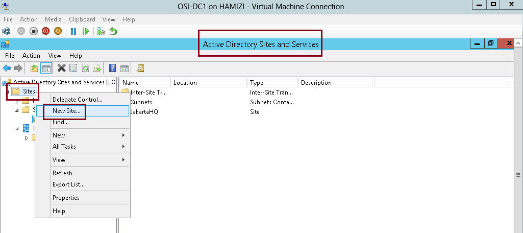
2 – In the New Object – Site dialog box, type Toronto then click DEFAULTIPSITELINK, and then click OK…
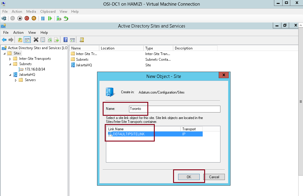
3 – click OK…

4 – repeat the previous step, but this time give a name as My-Test-Site…

5th – Create IP subnets associated with the Toronto sites
1 – In the Active Directory Sites and Services console, right-click Subnets, and then click New Subnet…

2 – In the New Object – Subnet dialog box, under Prefix, type 172.16.1.0/24, click Toronto, and then click OK…

3 – Right-click Subnets again, and then click New Subnet, under Prefix, type 172.16.100.0/24, then Under Select a site object for this prefix, click My-Test-Site, and then click OK…

4 – Verify in the details pane that the two subnets are created and associated with their appropriate site…

6th – Configure site-links between ADDS sites
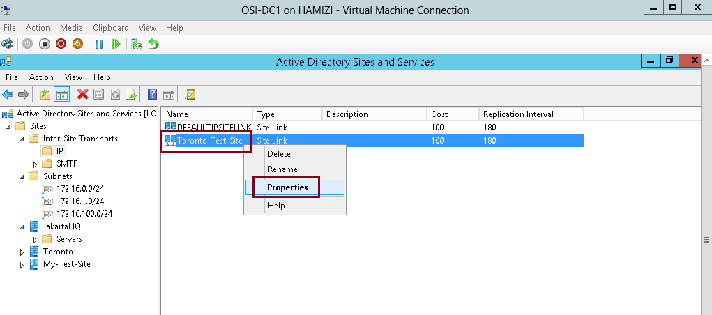
1 – In the Active Directory Sites and Services console, right-click IP, and then click New Site Link…

2 – In the New Object – Site Link box, type Toronto-Test-Site, then click Toronto and My-Test-Site, click Add…
3 – Then click OK…

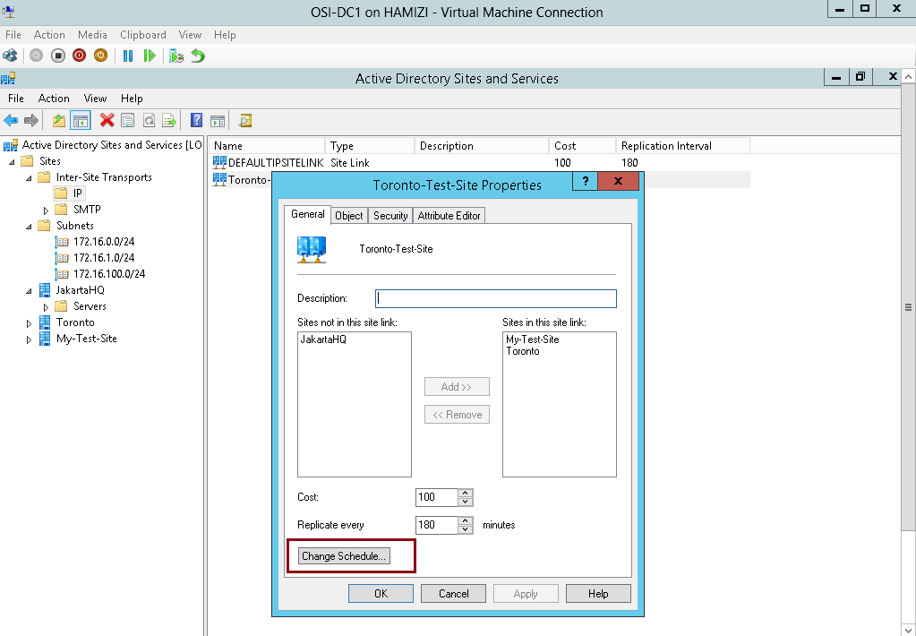
4 – Right-click Toronto-Test-Site, and then click Properties…
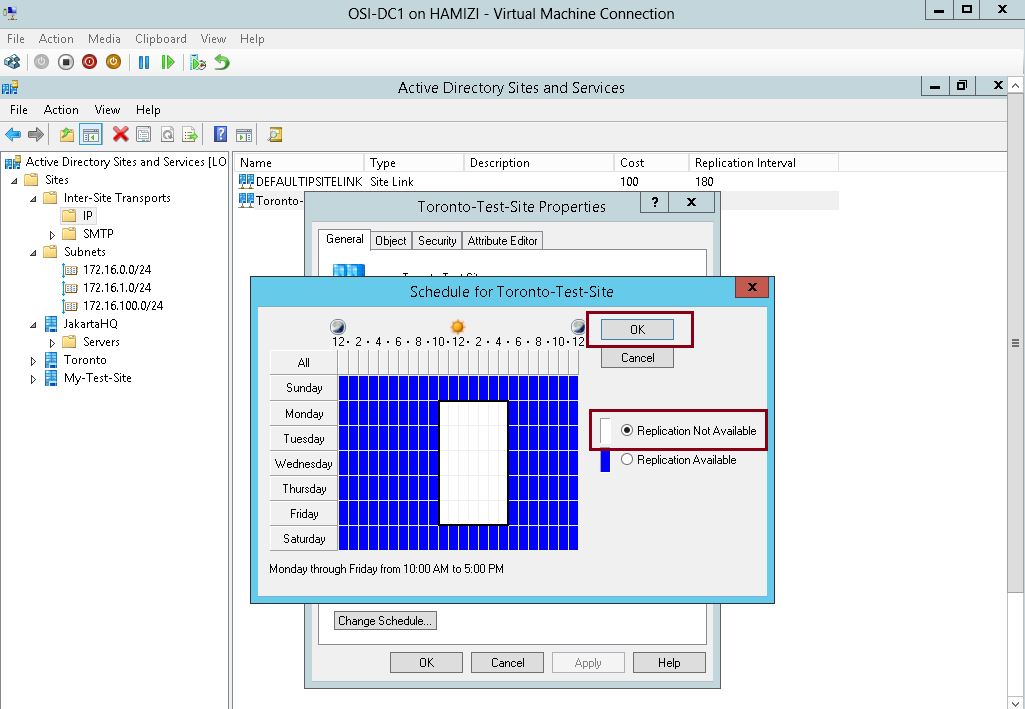
5 – then click Change Schedule…
6 – In the Schedule for Toronto-Test-Site box, highlight any range you prefer and then click Replication Not Available, and click OK…
7 – Next rename the DEFAULTIPSITELINK to LON-TOR…

8 – Next right-click LON-TOR, and then click Properties…

9 – Under Sites in this site link, click My-Test-Site, and then click Remove…

10 – Next to Replicate Every, change the value to 30 minutes, and then click OK…

7th – Move 2nd DC to the Toronto site
1 – In Active Directory Sites and Services console, right-click TOR-DC1, and then click Move…
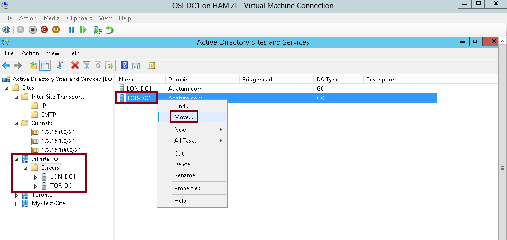
2 – In the Move Server box, click Toronto, and then click OK…

3 – Verify the TOR-DC1 listed under Toronto site…

8th – Monitor ADDS site replication
1 – On the DC01, open Windows PowerShell and then type Repadmin /kcc
** This command recalculates the inbound replication topology for the server.
** Knowledge Consistency Checker (KCC) helps generate and optimize the replication automatically between domain controllers within a site.
** type Repadmin /showrepl
— To display the replication connections of a domain controller and make sure you verify that the last replication with TOR-DC1 was successful…

2 – Next, type Repadmin /bridgeheads
** This command displays the bridgehead servers for the site topology…
then type : Repadmin /replsummary
** This command displays a summary of replication tasks. Verify that no errors appear…

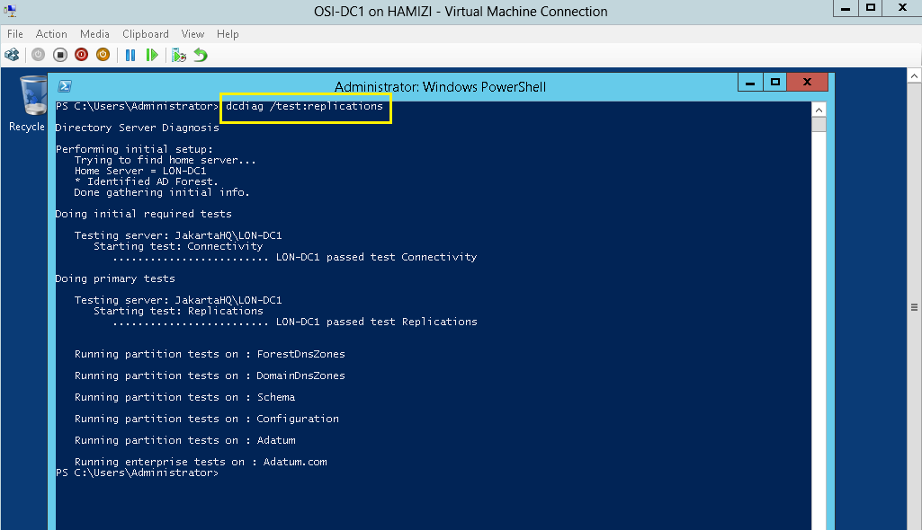
3 – Next, type DCDiag /test:replications
** Verify that all connectivity and replication tests pass successfully…
4 – Switch to the other Domain controller , and then repeat the same steps and that the last replication with LON-DC1 was successful.
That’s all for now… and you have succesfully configured site-links and monitored replication….
Branch offices have unique management challenges.
A branch office typically has slow connectivity to the enterprise network and limited infrastructure for securing servers.
In addition, you need to back up data that you maintain in your remote branch offices, which is why organizations prefer to centralize data where possible.
Therefore, the challenge is to provide efficient access to network resources for users in branch offices.
BranchCache helps you overcome these problems by caching files so they do not have to be transferred repeatedly over the network.
BranchCache improves the responsiveness of common network applications that access intranet servers
across slow WAN links.
Because BranchCache does not require additional infrastructure, you can improve the performance of remote networks by deploying Windows 7 or newer client computers, and by deploying Windows Server 2008 R2 or newer servers, and then enabling the BranchCache feature.
BranchCache maintains file and folder permissions to ensure that users only have access to files and
folders for which they have permission.
For more information, please log in to : http://technet.microsoft.com/en-us/library/hh831696.aspx
For this demo, i will be using 2 Server & 1 client PC, which is 1 Domain Server, 1 Member Server and 1 Windows 8 PC…
1st – Configure Domain Server to use Windows BranchCache
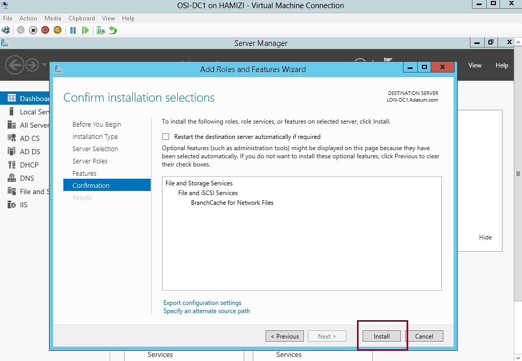
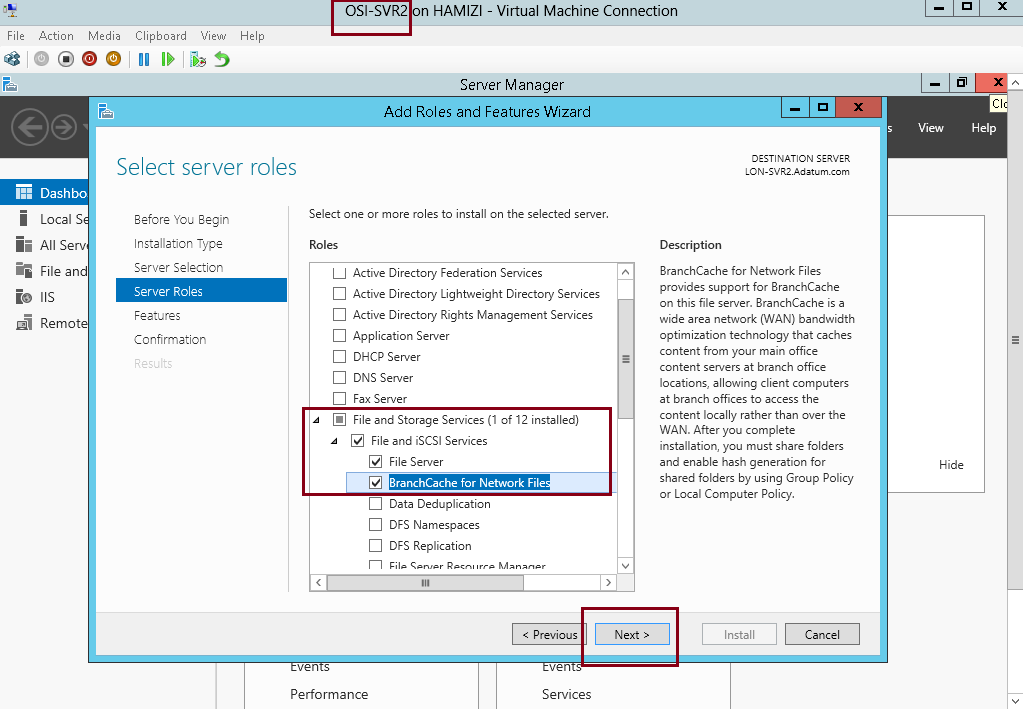
1 – On the DC01 server, open Server Manager, click Add roles and features and proceed installation until you reach Select server roles interface, and click BranchCache for Network Files, then proceed with Next…

2 – On the Select features interface, click Next…

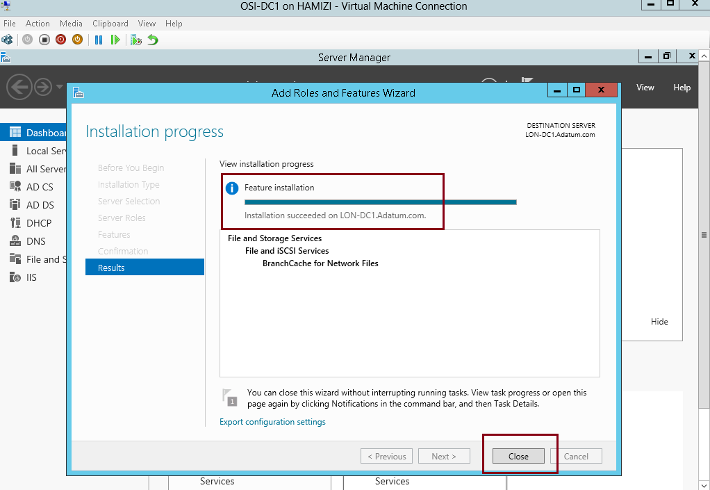
3 – On the Confirm installation selections interface, click Install…
4 – Once the installation complete, click Close…
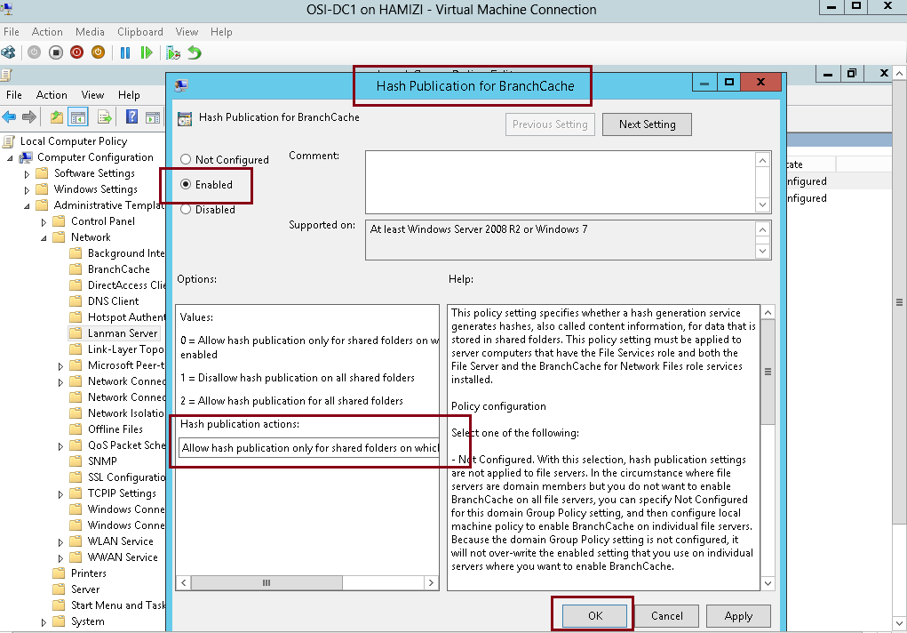
5 – Next, on the Domain Server open Gpedit.msc…
** In the Local Group Policy Editor console, under Computer Configuration, expand Administrative Templates, expand Network, and then click Lanman Server.
** On the Lanman Server result pane, double click Hash Publication for BranchCache…

6 – In the Hash Publication for BranchCache box, click Enabled, in the Hash publication actions list, select the Allow hash publication only for shared folders on which BranchCache is enabled, and then click OK…
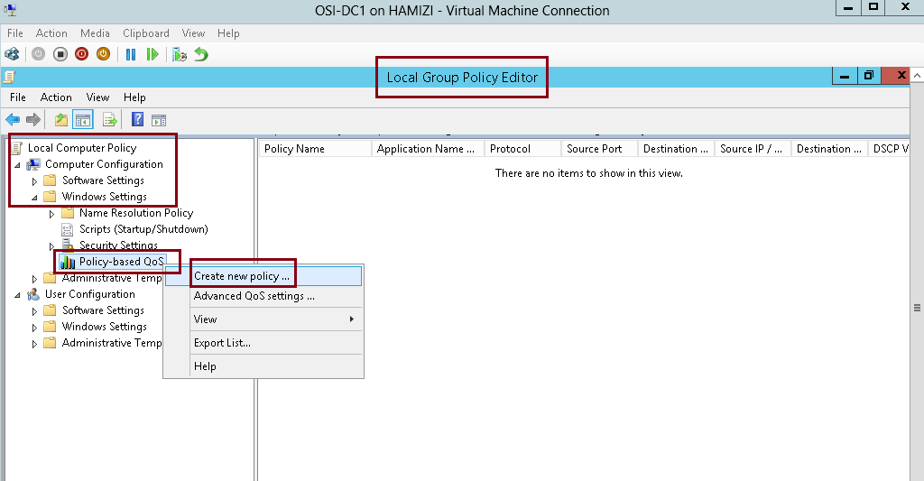
2nd – Simulate a slow link to the branch office
1 – Still in the Local Group Policy Editor console in Domain Server, in the navigation pane, under Computer Configuration, expand Windows Settings, right-click Policy-based QoS, and then click Create new policy…
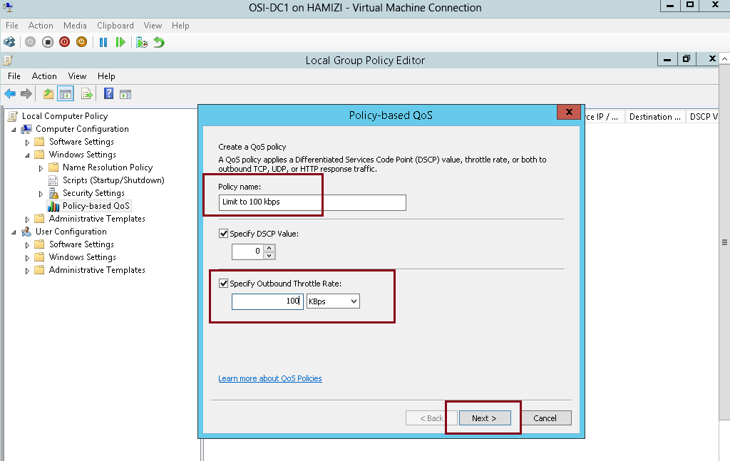
2 – In the Policy-based QoS Wizard, on the Create a QoS policy interface, in the Policy name text box, type Limit to 100 Kbps, and then select the Specify Outbound Throttle Rate check box. In the Specify Outbound Throttle Rate text box, type 100, and then click Next…
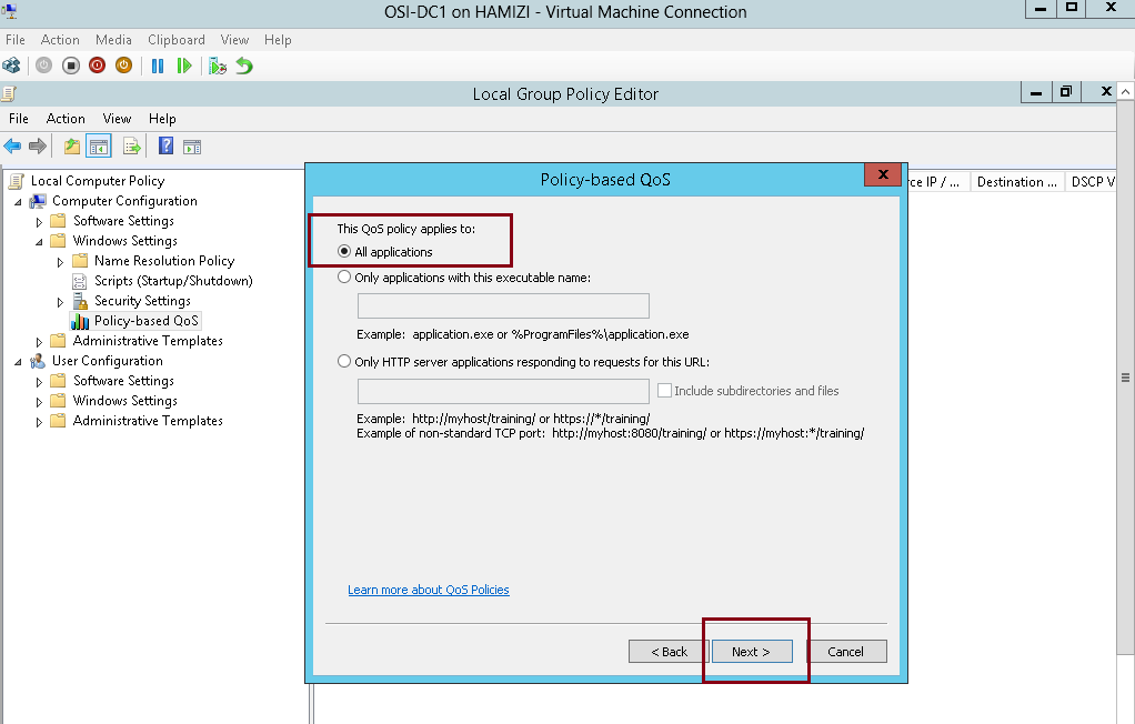
3 – On the This QoS policy applies to interface, click Next…
4 – On the Specify the source and destination IP addresses interface, click Next…
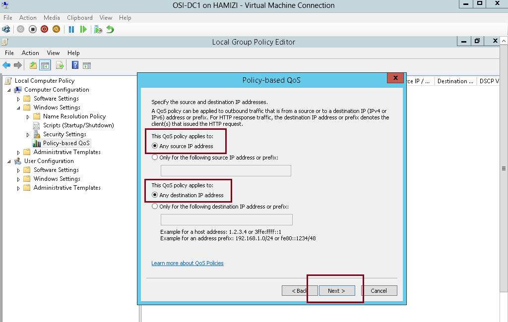
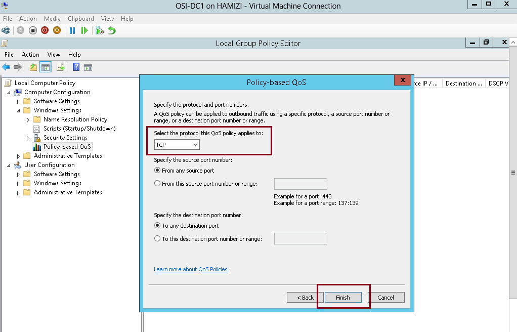
5 – On the Specify the protocol and port numbers interface, click Finish and close Local Group Policy Editor console…
3rd – Enable a File Share for BranchCache
1 – On the Domain Server DC01, create 1 folder called BC My_Share, and then share this folder…
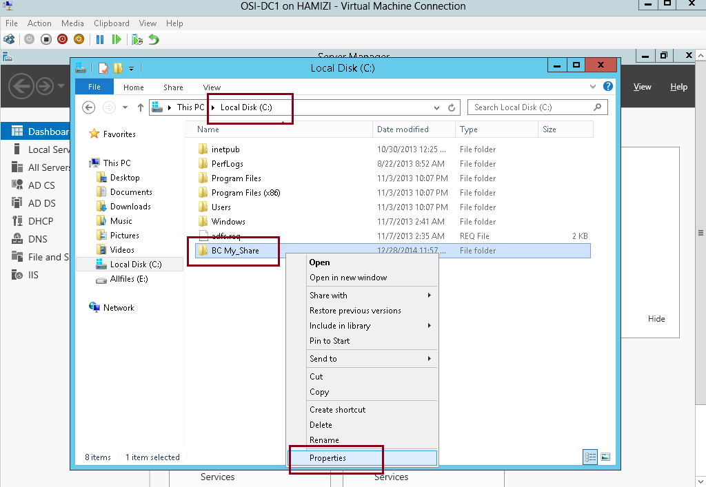
2 – On the BC My_Share properties, click Advanced Sharing…
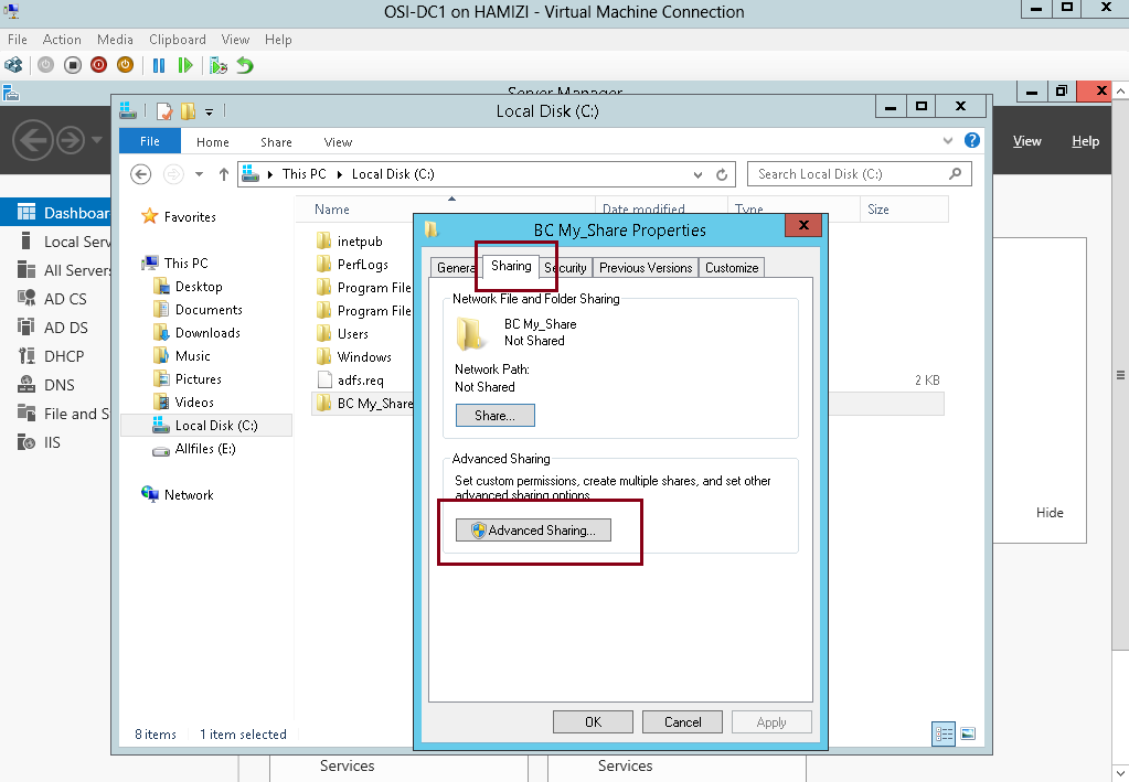
3 – Click Share this folder box, and click Caching…
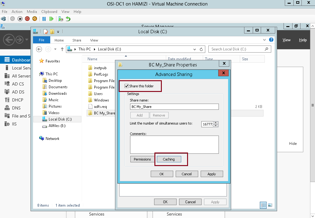
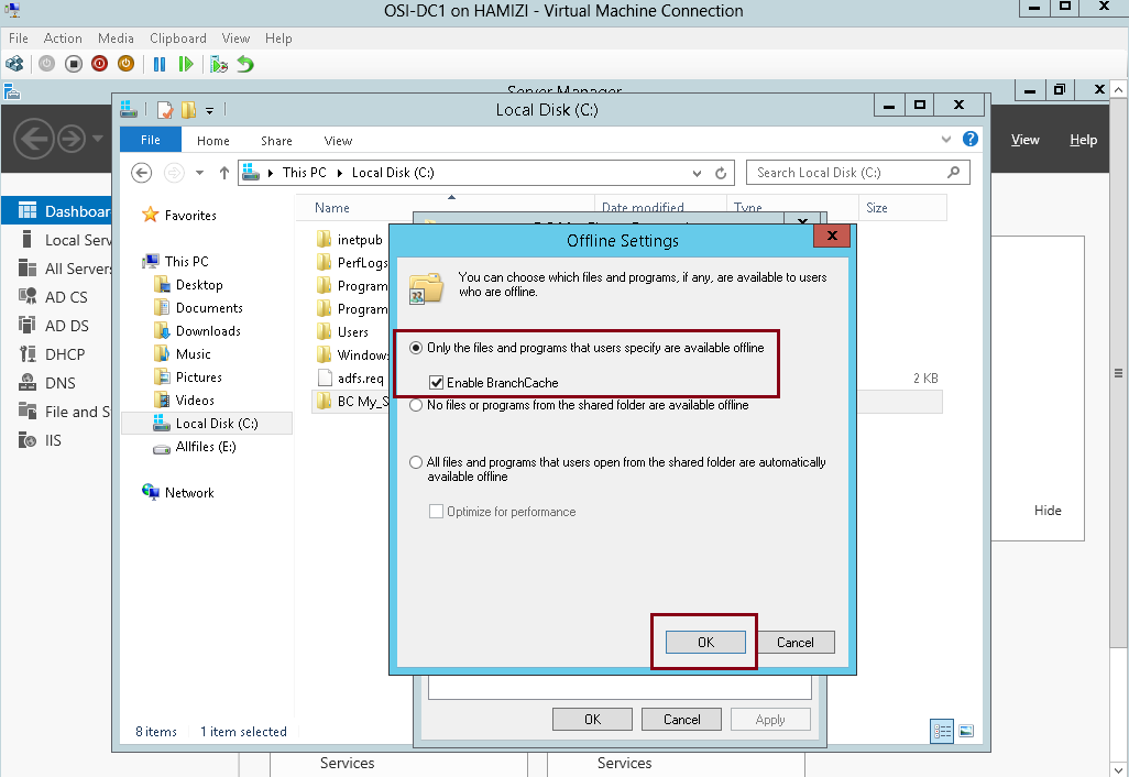
4 – In the Offline Settings box, click Enable BranchCache box, and then click OK…
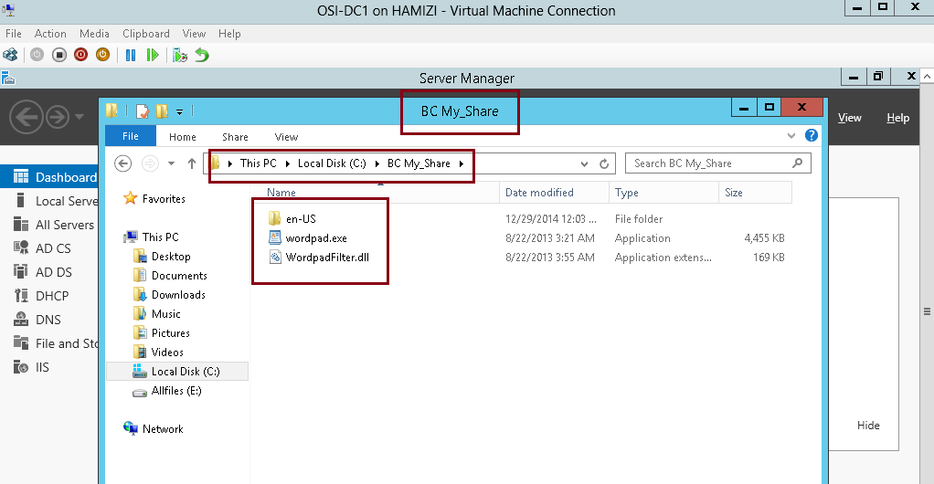
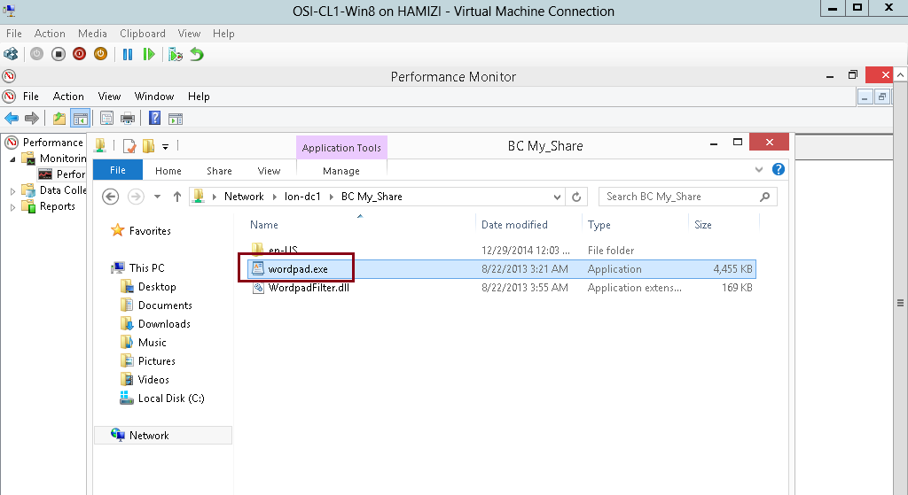
5 – Next, just simply copy any file and paste into the BC My_Share (for this demo i copy WordPad.exe)
4th – Configure client firewall rules for BranchCache
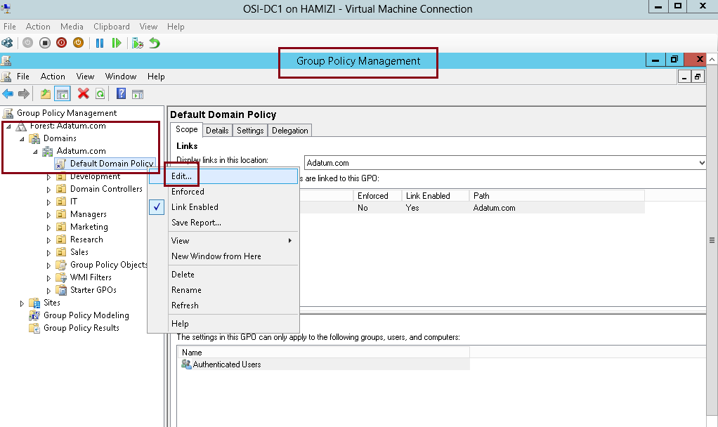
1 – In the Domain Server DC01, open Group Policy Management, then right-click Default Domain Policy, and then click Edit…
2 – In the Group Policy Management Editor, under Computer Configuration, expand Policies, expand Windows Settings, expand Security Settings, and then expand Windows Firewall with Advanced Security…
** expand Windows Firewall with Advanced Security, right-click Inbound Rules, and then click New Rule…

3 – In the New Inbound Rule Wizard, on the Rule Type page, click Predefined, click BranchCache – Content Retrieval (Uses HTTP), and then click Next…
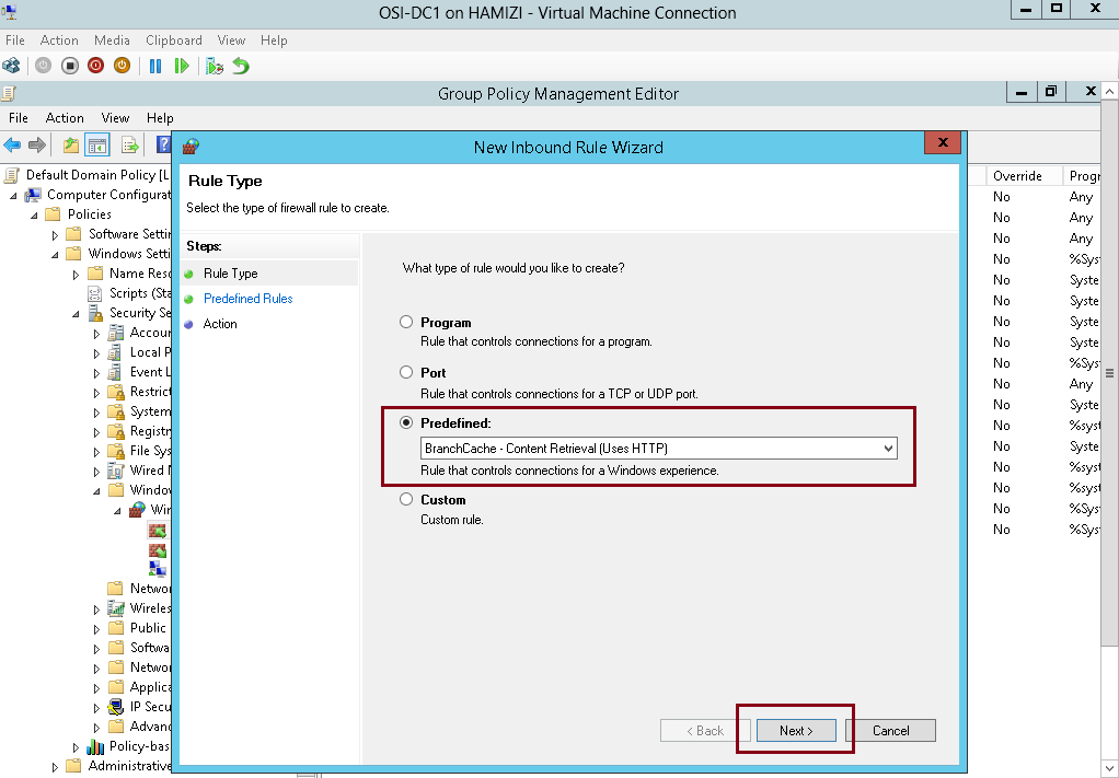
4 – On the Predefined Rules interface, click Next…
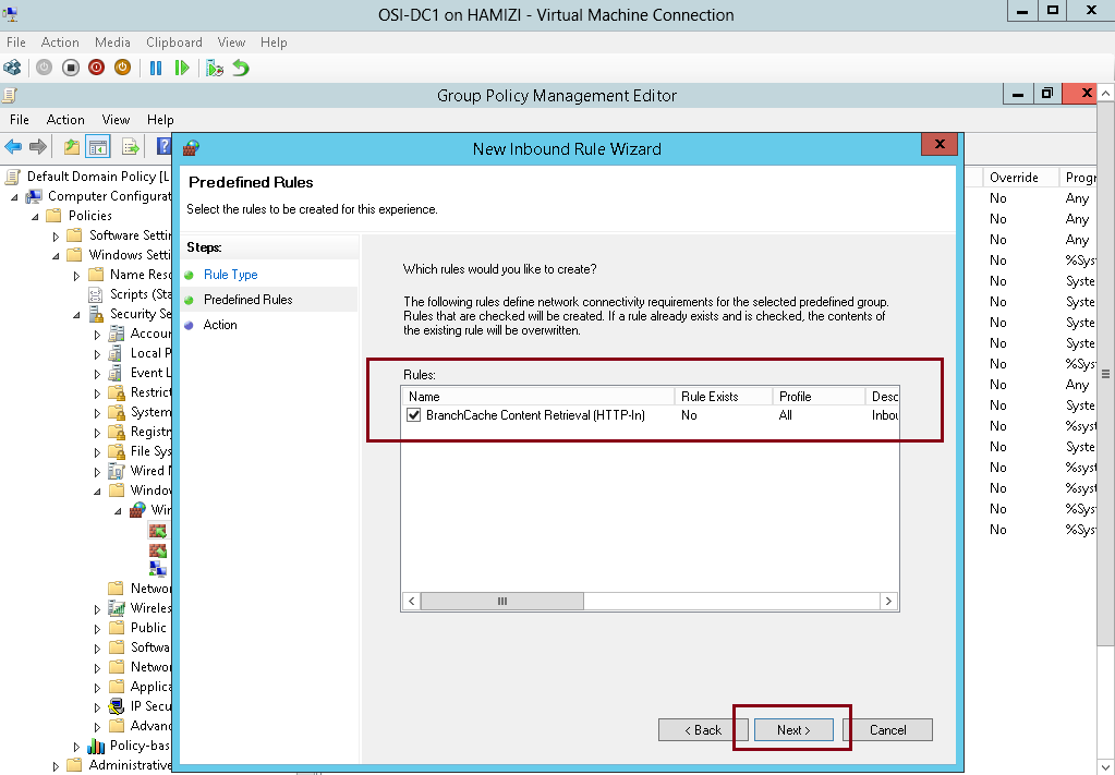
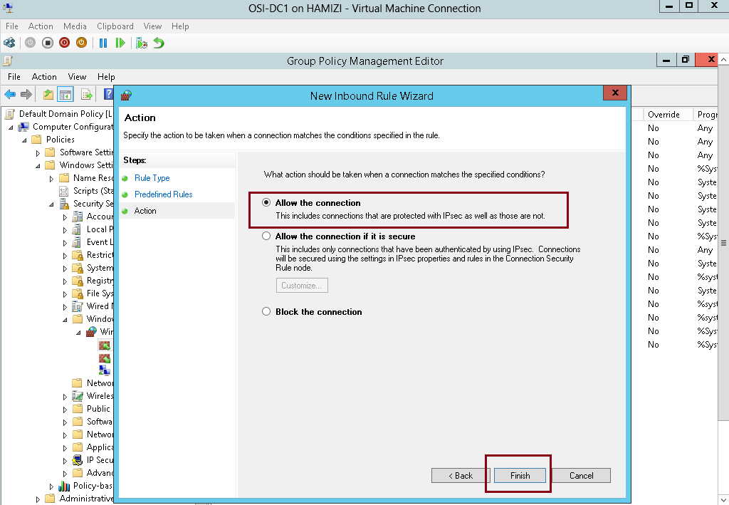
5 – On the Action page, click Finish to create the firewall inbound rule…
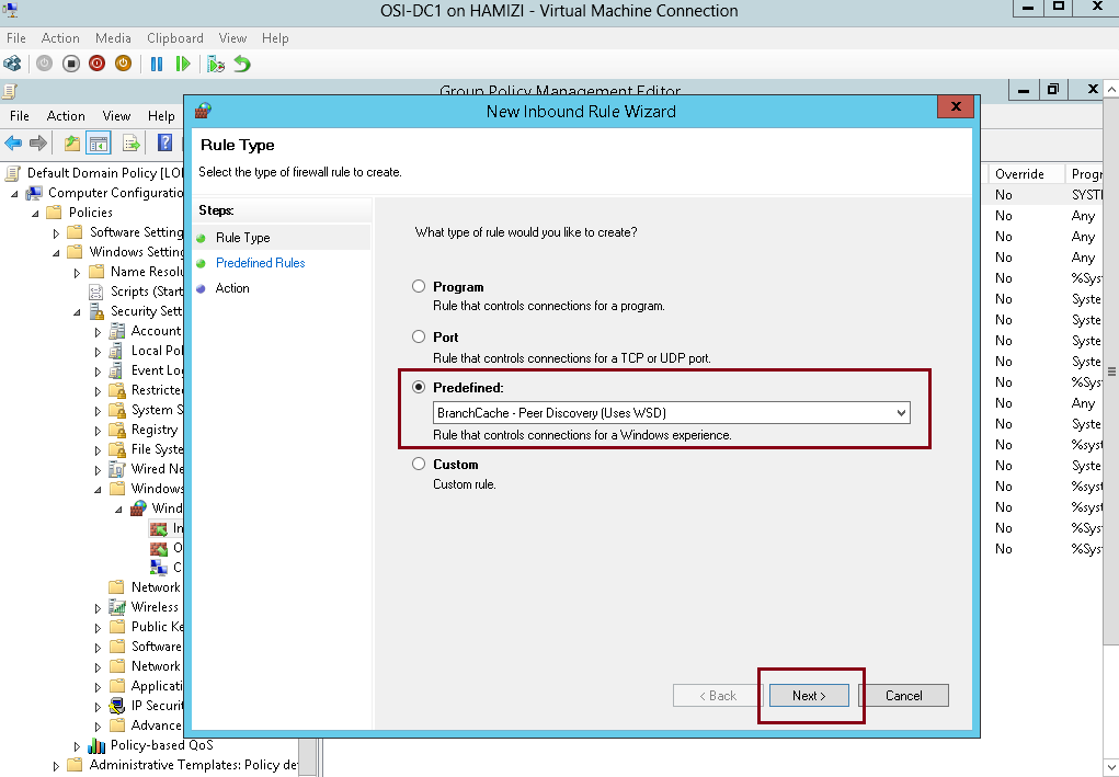
6 – Repeat the same step, and this time click Predefined, click BranchCache – Peer Discovery (Uses WSD), and
then click Next and proceed till Finish…
7 – Next, run gpupdate /boot /force command to activate the policy…

5th – Install BranchCache for Network Files role and the BranchCache feature on Member Server
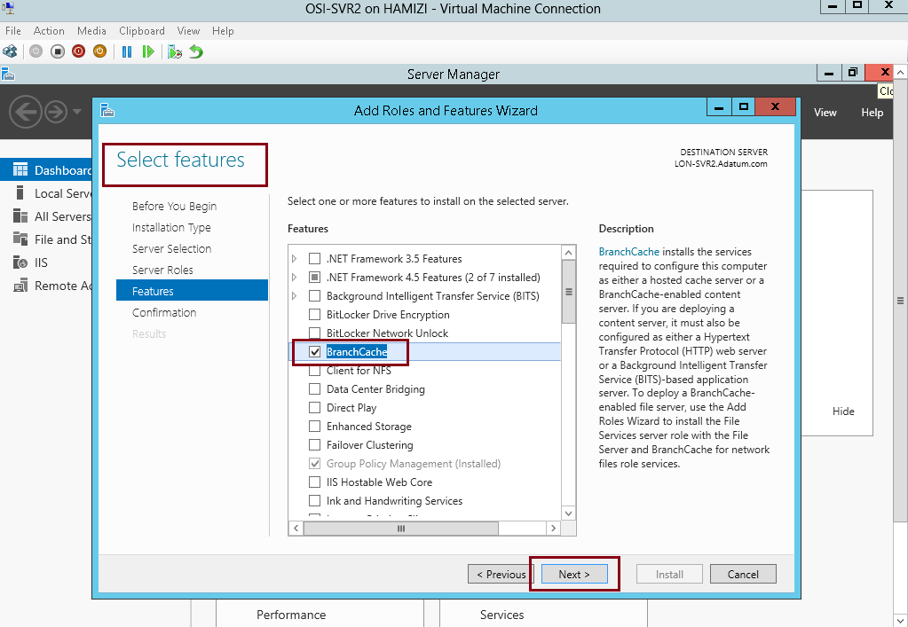
1 – Switch to member Server SVR2, open Server Manager, click Add roles and features and proceed installation to BranchCache for Network Files and proceed to Select Features….
2 – On the Select features interface, click BranchCache, and then click Next…
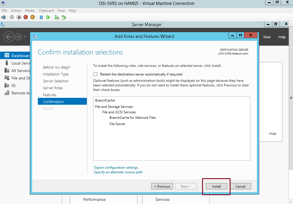
3 – On the Confirm installation selections interface, click Install, and then click Close….
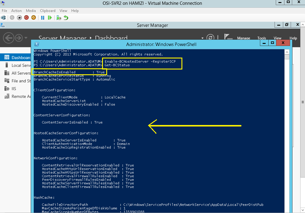
4 – Next, we need to start the BranchCache host server, in the SVR2 server open Windows PowerShell and type :
Enable-BCHostedServer -RegisterSCP
Get-BCStatus
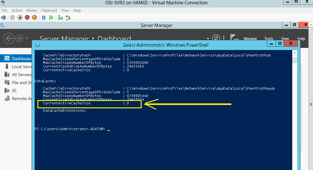
** verify that BranchCache is enabled and running…
5 – Scroll down to the DataCache section, notice the current active cache size is zero…
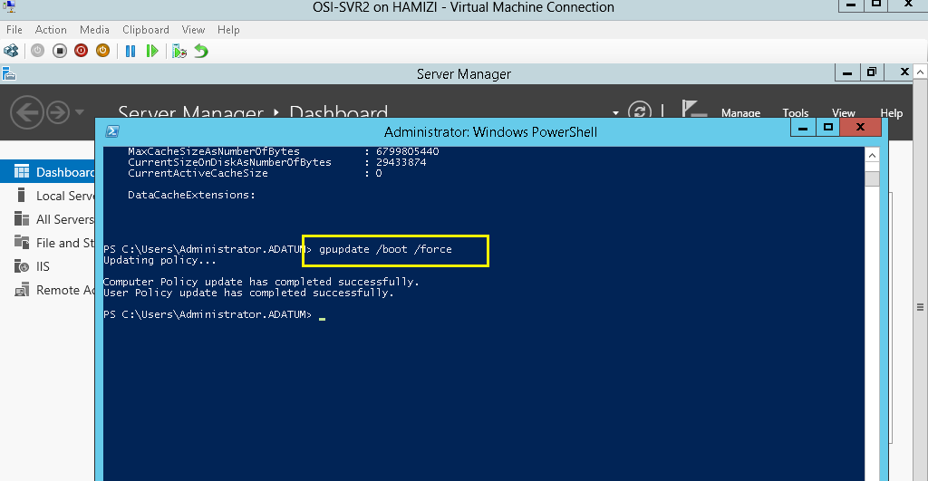
6 – Lastly run the gpupdate /boot /force…
6th – Configure client PC to use BranchCache in hosted cache mode
1 – On Domain Server DC01 open Group Policy Management, then right-click Adatum.com, and then click New Organizational Unit…
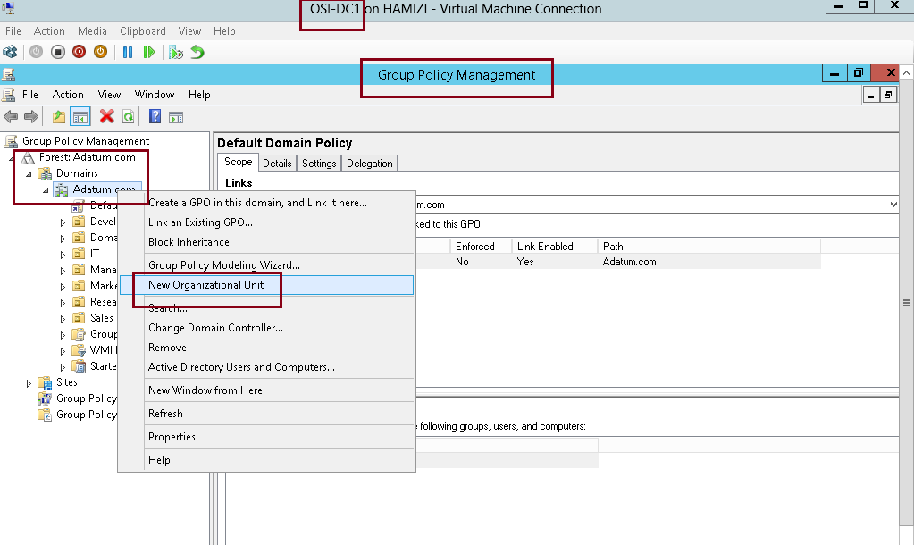
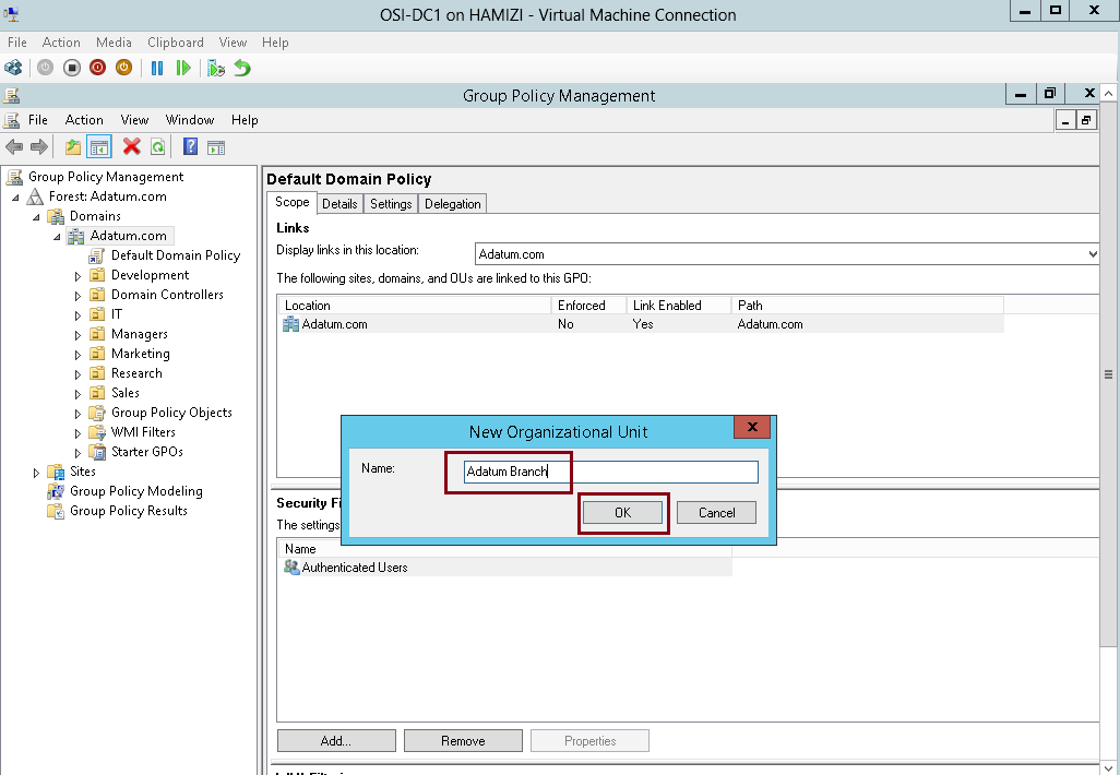
2 – In the New Organizational Unit box, type Adatum Branch and then click OK…
3 – Right-click the Adatum Branch OU and click Create a GPO in this domain, and link it here…
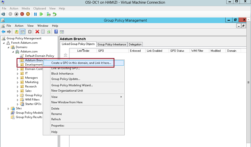
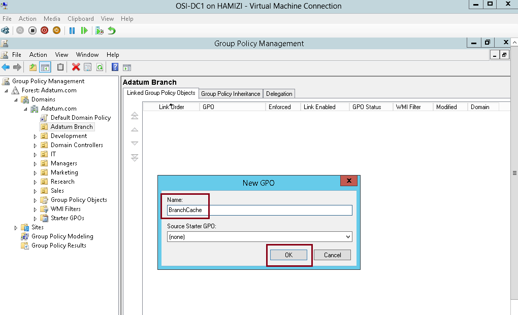
4 – In the New GPO box, type BranchCache, and then click OK…
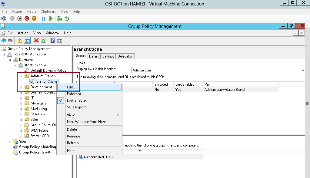
5 – Next, right-click the BranchCache GPO and click Edit…
6 – In the Group Policy Management Editor, under Computer Configuration, expand Policies, expand Administrative Templates, expand Network, and then click BranchCache…
** in the Setting list, double click BranchCache…
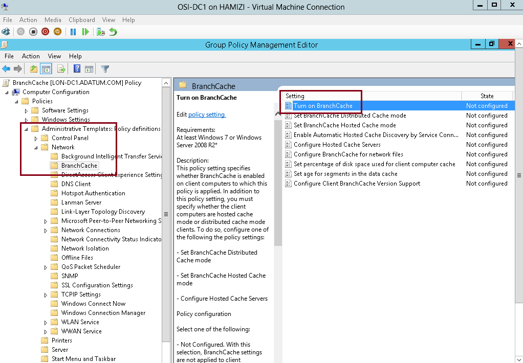
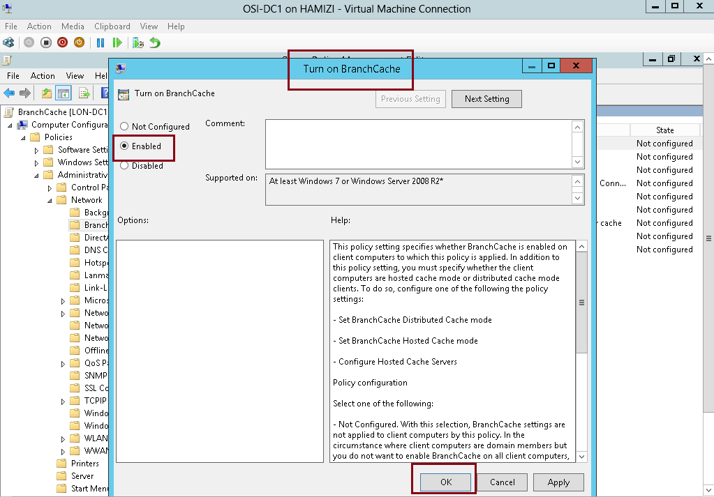
7 – In the Turn on BranchCache box, click Enabled, and then click OK…
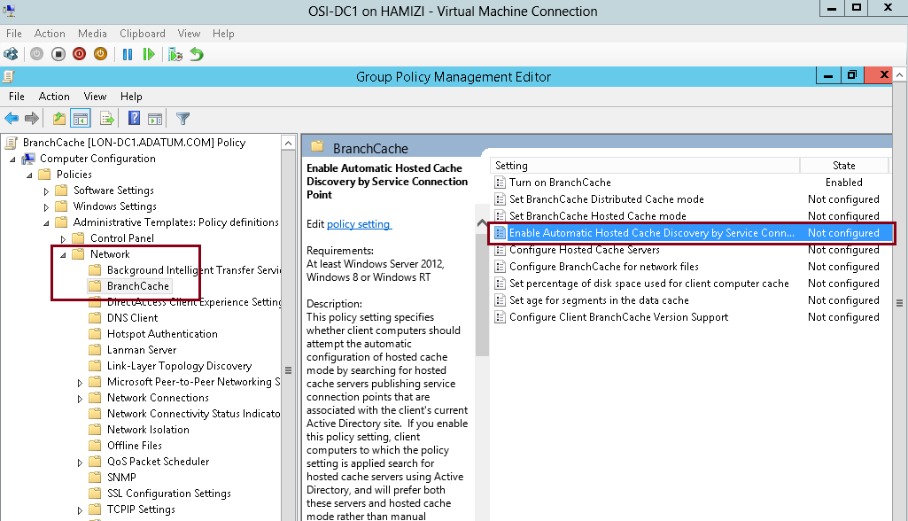
8 – In the BranchCache results pane, double click Enable Automatic Hosted Cache Discovery by Service Connection Point….
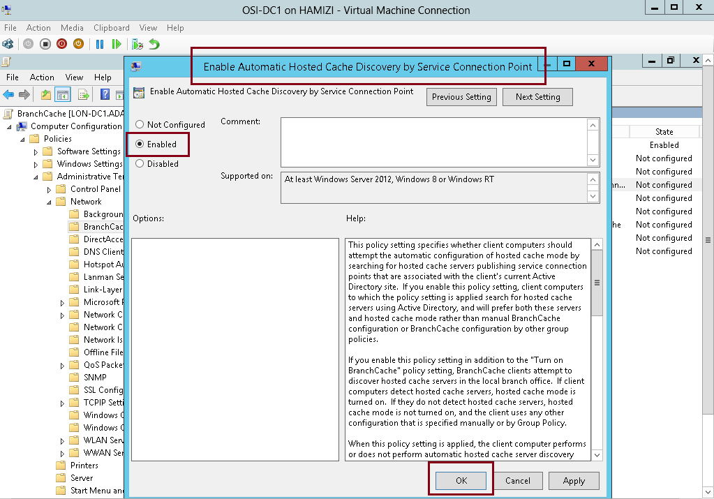
9 – In the Enable Automatic Hosted Cache Discovery by Service Connection Point box, click Enabled, and then click OK…
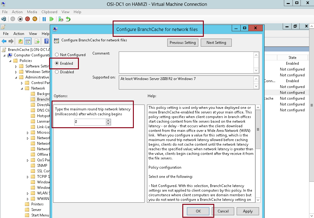
10 – In the BranchCache results pane, double click Configure BranchCache for network files, and then click Edit…
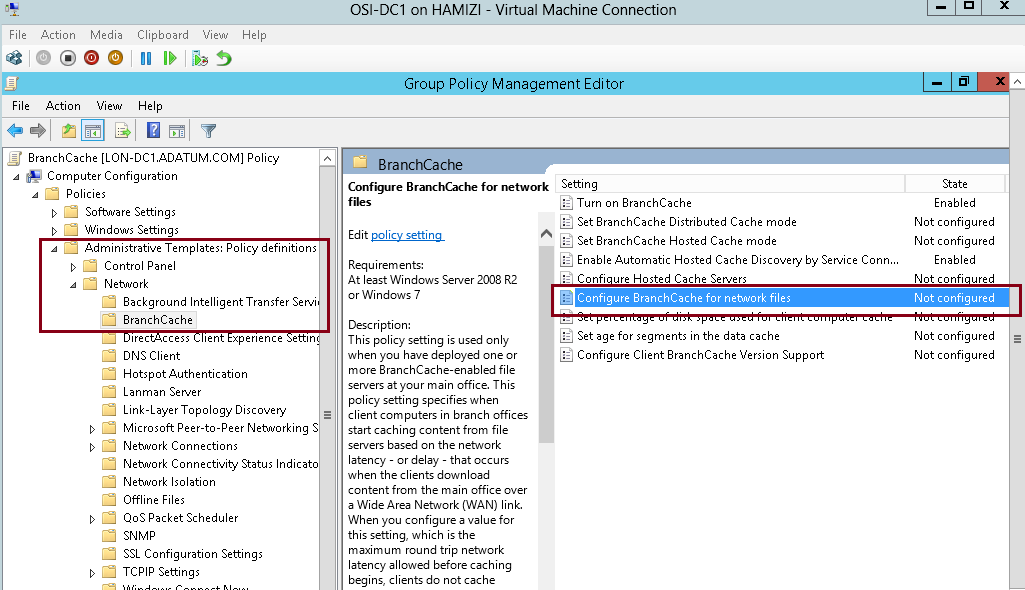
11 – In the Configure BranchCache for network files box, click Enabled, in the Type the maximum round trip network latency (milliseconds) after which caching begins text box, type 0, and then click OK.
“This setting is required to simulate access from a branch office and is not typically required…”
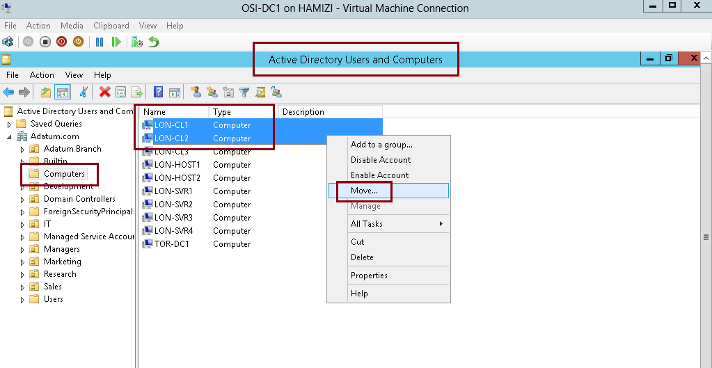
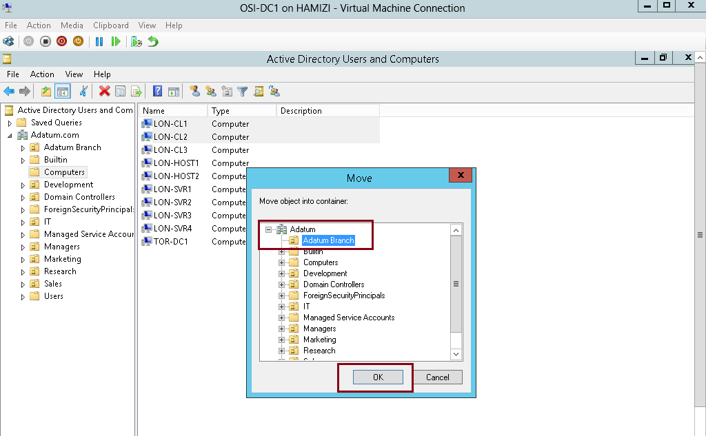
12 – Next, open Active Directory Users and Computers, and move any clients PC that you have in Computetr OU to Adatum Branch OU…
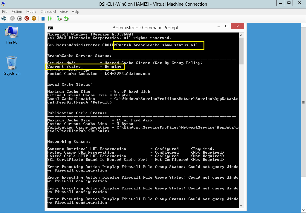
13 – Next, switch to Client PC, open CMD and type : netsh branchcache show status all
** Verify that the BranchCache Current Status is Running. If the status is Stopped, restart the client machines.
7th – Monitoring BranchCache
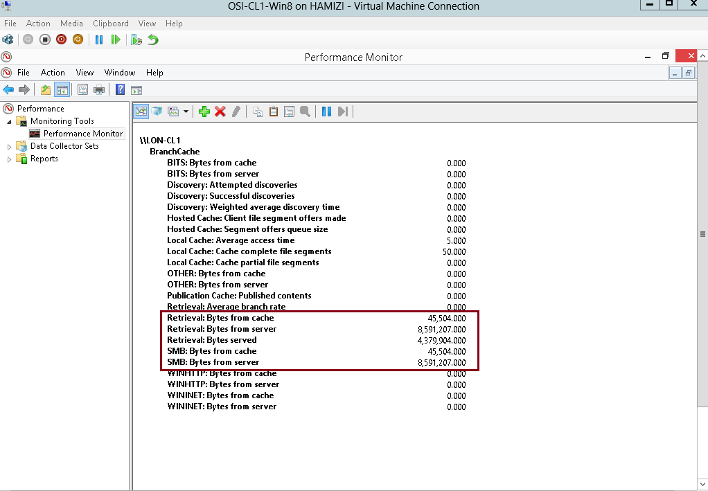
1 – Switch to SVR2 Server and open Performance Monitor…
** under Monitoring Tools, click Performance Monitor, then click the Add icon…
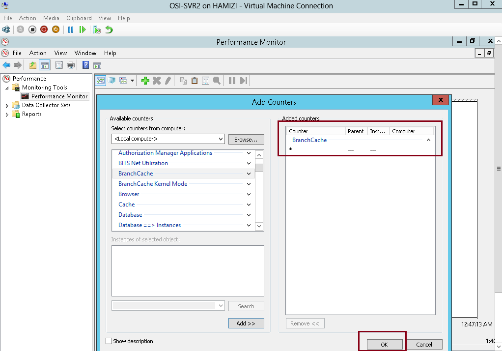
** In the Add Counters box, under Select counters from computer, click BranchCache, click Add…
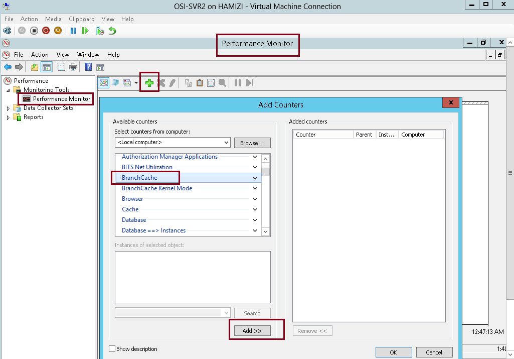
2 – and then click OK…
3 – On the Change Graph type button, select Report…
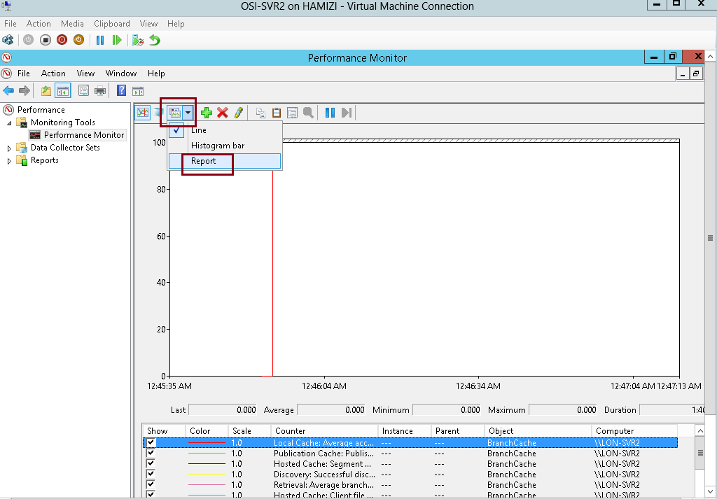
4 – Switch to Client PC, and repeat the step previously for Performance Monitor & add BranchCache….
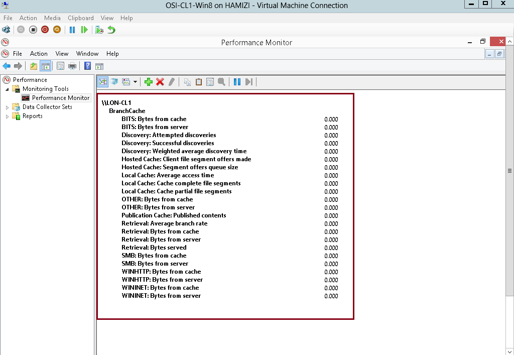
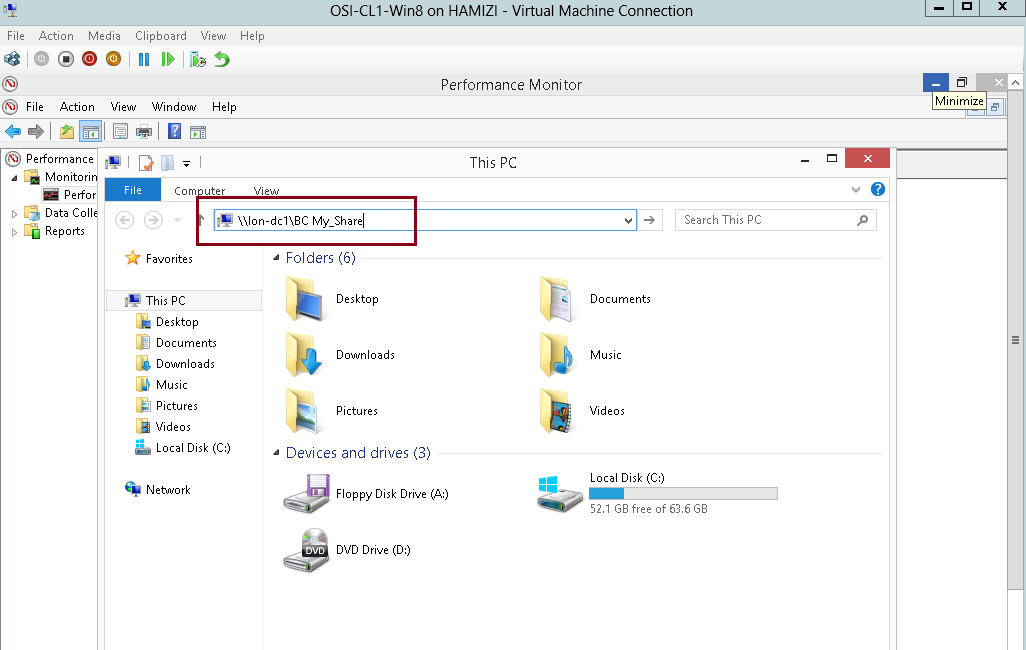
5 – Now lets the BranchCache, on the client PC, access to \\lon-dc1\BC My_Share folder….
6 – Copy the whole file in the BC My_Share folder and then paste to your client PC desktop…
7 – Read the performance statistics on client PC.
** This file was retrieved from LON-DC1 (Retrieval: Bytes from Server).
** After the file was cached locally, it was passed up to the hosted cache. (Retrieval: Bytes Served)
that’s all for now.. i hope you all enjoy the demo on the BranchCache…
Network Load Balancing (NLB) is a feature available to computers that run the Windows Server operating system. NLB uses a distributed algorithm to balance an IP traffic load across multiple hosts. It helps to improve the scalability and availability of business-critical, IP-based services. NLB also provides high availability, because it detects host failures and automatically redistributes traffic to surviving hosts.
Before you deploy NLB, you need to have a firm understanding of the types of server workloads for which this high availability technology is appropriate. If you do not understand NLB functionality, you might deploy it in a manner that does not accomplish your overall objectives. For example, you need to understand why NLB is appropriate for web applications, but not for Microsoft SQL Server databases.
For more information : Please log in to : http://technet.microsoft.com/en-us/library/cc732855(v=ws.10).aspx
For this NLB demo this time, i will be using 3 Server, which is 1 Domain Server and 2 Member Server.
1st – In the 1st step lets implementing an NLB Cluster
1 – Before we continue with the deployment, we need to verify our website functionality…
2 – To verify our website functionality, log in to SVR01 server, open iis file (which is in the format of .bmp), the file suppose to be located in c:\inetpub\wwwroot.
3 – To simulate this demo, please make some adjustment to the iis.bmp file (Refer to pic), and then save the iis file.

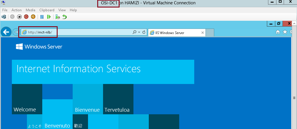
4 – Now switch to Domain Server (DC01), open IE and type the address http://LON-SVR1.
** Verify that the webpage displays the IIS logo with the yellow color mark that you added…
5 – Still in the IE, enter the address http://LON-SVR2, and then press Enter. Verify that the webpage does not display the marked IIS logo.

2nd – Our next step is to Install NLB services
1 – Now switch to LON-SVR1 server and open Windows PowerShell ISE…

2 – In the Windows PowerShell ISE type :
Invoke-Command -Computername LON-SVR1,LON-SVR2 -command {Install-WindowsFeature NLB,RSAT-NLB}

3 – Once the process complete, open Server Manager, click Tools and verify that Network Load Balancing Manager is installed…

4 – Now switch to SVR2, open Server Manager, click Tools and verify also that Network Load Balancing Manager is installed…

3rd – Create a new Windows Server 2012 NLB cluster
1 – On SVR1 server, in the Windows PowerShell ISE, type :
New-NlbCluster -InterfaceName “Ethernet” -OperationMode Multicast -ClusterPrimaryIP 172.16.0.42 -ClusterName MCT-NLB

2 – Once the command complete, still in the Windows PowerShell ISE, type :
Invoke-Command -Computername LON-DC1 -command {Add-DNSServerResourceRecordA – zonename adatum.com –name MCT-NLB –Ipv4Address 172.16.0.42}

3 – Now to add add a second host to the cluster, still in Windows PowerShell ISE, type :
Add-NlbClusterNode -InterfaceName “Ethernet” -NewNodeName “LON-SVR2” – NewNodeInterface “Ethernet”

4th – Its time to validate the NLB cluster…
1 – On the SVR1 Server, open Server Manager, click the Tools, and then click Network Load Balancing Manager…

2 – In the Network Load Balancing Manager console, verify that nodes LON-SVR1 and LON-SVR2 display with the status of Converged for the MCT-NLB cluster.

3 – Next, right-click the MCT-NLB cluster, and then click Cluster properties…

4 – In the MCT-NLB(172.16.0.42), on the Cluster Parameters tab, verify that the cluster is set to use the Multicast operations mode…

5 – On the Port Rules tab, verify that there is a single port rule named All that starts at port 0 and ends at port 65535 for both TCP and UDP protocols, and that it uses Single affinity…

4th – Configuring and Managing the NLB Cluster
1 – Before we start configure and manage the NLB Cluster, log on to SVR2 server, and create 1 folder named porttest in C:\
2 – then copy all c:\inetpub\wwwroot to c:\porttest folder
3 – Open PowerShell and type :
New-Website –Name PortTest –PhysicalPath “C:\porttest” –Port 5678
New-NetFirewallRule –DisplayName PortTest –Protocol TCP –LocalPort 5678

4 – Next, open porttest folder, and then double-click iis file…

5 – Make some modification to mark the IIS logo and save the file…

6 – Now switch to Domain Server and in the IE type http://LON-SVR2:5678…
** Verify that the IIS Start page with the IIS logo distinctively marked with RED displays.

7 – Now switch back to SVR1 server and open Network Load Balancing Manager, in the Network Load Balancing Manager console, right-click MCT-NLB, and then click Cluster Properties…
** In the MCT-NLB(172.16.0.42), on the Port Rules tab, select the All port rule, and then click Remove…

8 – On the Port Rules tab, click Add…

9 – In the Add/Edit Port Rule box, enter the following information, and then click OK:
• Port range: 80 to 80
• Protocols: Both
• Filtering mode: Multiple Host
• Affinity: None

10 – On the Port Rules tab, click Add again….
** In the Add/Edit Port Rule box, enter the following information, and then click OK:
• Port range: 5678 to 5678
• Protocols: Both
• Filtering mode: Single Host

11 – Click OK to close the MCT-NLB(172.16.0.42)…

12 – In the Network Load Balancing Manager console, right-click LON-SVR1, and then click Host Properties…

13 – On the Port Rules tab, click the port rule that has 5678 as the Start and End value, and then click Edit…

14 – Click the Handling priority value, and change it to 10 and click OK twice to close…

5th – Validate port rules
1 – To validate port rules, switch to DC01 Server, in IE type http://mct-nlb, and then Refresh the site few times and verify that you see web pages with and without the distinctive Yellow marking.

2 – Next, still in IE enter the address http://mct-nlb:5678 and and then Refresh the site few times and verify that you see web site with the RED marking…

6th : Manage host availability in the NLB cluster
1 – Switch to SVR1 server, in the Network Load Balancing Manager console, right-click LON-SVR1, click Control Host, and then click Suspend…

2 – Click the MCT-NLB node.
** Verify that node LON-SVR1 displays as Suspended, and that node LONSVR2 displays as Converged.
3 – Right-click LON-SVR1, click Control Host, and then click Resume…

4 – Right-click LON-SVR1, click Control Host, and then click Start…

5 – Click the LON-NLB node.
** Verify that both nodes LON-SVR1 and LON-SVR2 now display as Converged. You might have to refresh the view…

6th : Validate website availability when the host is unavailable
1 – Restart SVR1 server and then switch to DC01 server and in the IE type http://mct-nlb..
** Refresh the website few times.
** Verify that the website is available while SVR1 reboots, but that it does not display the distinctive YELLOW mark on the IIS logo until SVR1 has restarted.
While SVR1 restarted..
After SVR1 restarted…

2 – Once the SVR1 restarted, log in and open Network Load Balancing Manager, in the Network Load Balancing Manager console, right-click LON-SVR2, click Control Host, and then click Drainstop…
** Then switch back to DC01 and refresh the website few times and verify that in the website YELLOW IIS logo displays
** The Drainstop action blocks all new connections without terminating existing sessions

Failover clusters in Windows Server 2012 provide a high-availability solution for many server roles and applications.
By implementing failover clusters, you can maintain application or service availability if one or more computers in the failover cluster fails.
There are a lot of information that you can digest on the Failover Clustering, for more information please log in to :
http://technet.microsoft.com/en-us/library/hh831579.aspx
For this Failover Clustering demo, i will be using 4 VM’s, which is domain controller and 3 member server. Please refer to the screenshot :

1st : our 1st step is to configure a Failover Cluster, which is in this step i will connect a cluster nodes to the iSCSI targets…
Scenario for this demo is very simple :
“Your organization has important applications and services that the company wants to make highly available.
Some of these services cannot be made redundant by using NLB, so you decide to implement failover clustering.
Because iSCSI storage is already in-place, you decide to use the iSCSI storage for failover clustering.
First, you will implement the core components for failover clustering and validate the cluster, and then you will
create the failover cluster.”
1 – For this configuration i will be using my OSI-SVR3 member server, on OSI-SVR3, open Server Manager, click Tools, and then click the iSCSI Initiator…

2 – In the Microsoft iSCSI interface, just click Yes…

3 – on the iSCSI initiator Properties interface, click the Discovery tab and then click Discover Portal…
** Internet SCSI (iSCSI) initiator –> to established a connection with an iSCSI target

4 – In the IP address or DNS name box, type 172.16.0.21, and then click OK…
172.16.0.21 – OSi-SVR1 server

5 – Next, click the Targets tab, and click Refresh…
** In the Targets list, select iqn.1991-05…., and then click Connect…

6 – then cllick Add this connection to the list of Favorite Targets, and then click OK two times…

** Please repeat the step 1 – 6 on your SVR4 server…
7 – Switch to SVR3 and open Computer Management and make sure that you have few disk already attach to your Server to stimulate this demo, for this demo i have 3 VHD that i attach previously on the SVr3 server, all 3 disk having 30GB space each, you may choose your own space.

8 – Switch to SVR4 and please make sure also that you have the same disk configuration…
** make sure that all the disk is online (Right-click Disk 1, and then click Online)….

2nd : Let install the failover clustering feature on our SVR3 server….
1 – Open Server Manager and continue with add roles & feature until you reach Select features interface, then click Failover Clustering and continue with installation…

2 – next on the Confirm installation selections interface, click Install…

3 – Once installation complete, click Close…

** Repeat steps 1 – 3 on SVR4 server…
4 – Now we need to validate the both servers for failover clustering, on the SVR3 server open Failover Cluster Manager…

5 – On the right pane of Failover Cluster Manager, click Validate Configuration…

6 – In the Validate a Configuration Wizard interface, click Next…

7 – On the Select Servers or a cluster interface, please add our SVR3 & SVR4 and then click Next…

8 – On the Testing options interface, click Run all tests (recommended) and then click Next…

9 – On the Confirmation interface, click Next…
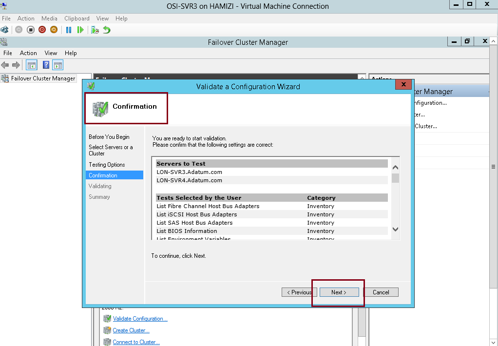
10 – This process might take up to 5 – 10 minutes…

11 – Once the validation tests to finish, on the Summary page, click View Report…

12 – Just verify that all tests completed…

3rd : Our next step is to create the failover cluster…
1 – in the Failover Cluster Manager, click Create Cluster….

2 – then click Next…

3 – On the Select Servers interface, make sure you add SVR3 & SVR4 in the selected servers and then click Next…

4 – In Access Point for Administering the Cluster interface, in the Cluster Name box, type OSICluster1.
** Under Address, type 172.16.0.125, and then click Next.

5 – In the Confirmation box, verify the information, and then click Next…

6 – On the Summary interface, click Finish…

4th : Configuring CSV
” Cluster Shared Volumes (CSV) enable multiple nodes in a failover cluster to simultaneously have read-write access to the same LUN (disk) that is provisioned as an NTFS volume.
With CSV, clustered roles can fail over quickly from one node to another node without requiring a change in drive ownership, or dismounting and remounting a volume.
CSV also help simplify the management of a potentially large number of LUNs in a failover cluster.”
1 – On SVR3 server, in the Failover Cluster Manager console, expand cluster1.Adatum.com, expand Storage, and then click Disks.
** locate a disk that is assigned to Available Storage. You can see this in the Assigned To column.
** Right-click that disk, and then click Add to Cluster Shared Volumes.
** Verify that the disk is assigned to Cluster Shared Volume…

5th : Our next step is to deploy and configure Highly Available File Server…
1 – On the SVR4 server, open Server Manager, click add roles & features and continue to Select server roles and then select File Server, then click Next 2 times…

2 – On the Confirmation interface, click Install…

3 – Next, switch back to SVR3 server, in the Failover Cluster Manager, expand Cluster1.adatum.com, right-click Roles, and then select Configure Role…

4 – click Next…

5 – On the Select Role interface, select File Server, and then click Next….
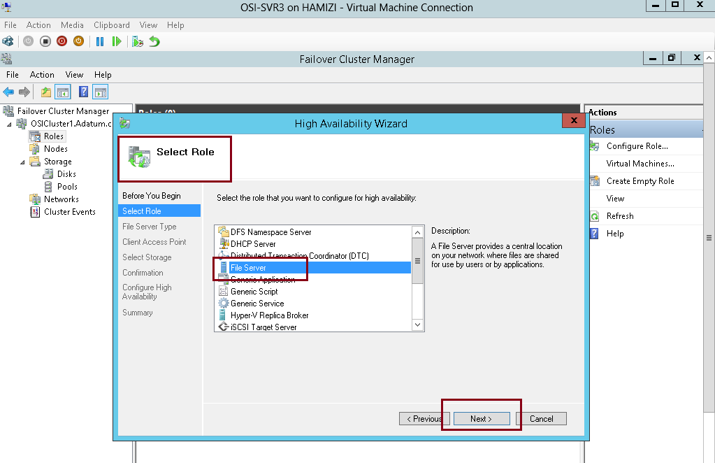
6 – On the File Server Type interface, click File Server for general use, and then click Next…

7 – On the Client Access Point interface, in the Name box, type OSI-FS, in the Address box, type 172.16.0.130, and then click Next…

8 – On the Select Storage interface, select the Cluster Disk 3 check box, and then click Next…

9 – On the Confirmation interface, click Next…

10 – click Finish…

6th : Next we going to add a shared folder to a highly available File Server…
1 – Switch to SVR4 server and open Failover Cluster Manager…
** Expand Cluster1.Adatum.com, and then click Roles.
** Right-click OSI-FS, and then select Add File Share…

2 – In the Select the profile for this share interface, click SMB Share – Quick, and then click Next…

3 – On the Select the server and the path for this share interface, verify the server & Volume to share and then click Next…

4 – On the Specify share name interface, in the Share name box, type OSI-Docs, and then click Next…

5 – On the Configure share settings interface, do not make any changes, and then click Next…

6 – On the Specify permissions to control access interface, click Next…

7 – On the Confirm selections interface, click Create…

8 – On the View results interface, click Close…

9 – Next we need to configure failover and failback settings, on the Failover Cluster Manager, click Roles, right-click OSI-FS, and then click Properties…
“** Failover transfers the responsibility of providing access to resources in a cluster from one node to another. Failover can occur when an administrator intentionally moves resources to another node for maintenance, or when unplanned downtime of one node happens because of hardware failure or other reasons. In addition, service failure on an active node can initiate failover to another node.”
“** The Cluster service can failback instances that were originally hosted on the offline node after the offline node becomes active again. When the Cluster service fails back an instance, it follows the same procedures that it performs during failover. That is, the Cluster service takes all the resources in the instance offline, moves the instance, and then brings all the resources in the instance back online.”

10 – Click the Failover tab and then click Allow failback…
** Click Failback between, and set values to 3 and 4 hours.

11 – Next, click the General tab, then select SVR3 and SVR4 as preferred owners and make sure you move SVR4 up, then click OK…

7th : Now we have to validate / verify the Deployment of our High Availability File Server
1 – Switch to DC01 server (Domain Server), try access to \\osi-fs\osi-docs…
** Verify that you can access the location and that you can open the osi-docs folder…

2 – To verify you can create a any text document inside this folder…

3 – Next, switch back to SVR3 server and open the Failover Cluster Manager.
** Expand Cluster1.adatum.com, and then click Roles. Note the current owner of OSI-FS (SVR3)
** Right-click OSI-FS, click Move, and then click Select Node…

4 – In the Move Clustered Role box, select the cluster node (it will be either SVR3 or SVR4), and then click OK…

5 – Verify that SVR4 has moved to a new owner…
** I do recommend that you switch back to DC1 server and verify that you can still access the \\osi-fs\osi-docs…

6 – Next, in the Failover Cluster Manager, right-click the node (I choose SVR4) , select More Actions, and then click Stop Cluster Service…

7 – Verify that SVR4 now is down…

8 – Verify also OSI-FS has moved to another node which is SVR3…
** ** I do recommend that you switch back to DC1 server again and verify that you can still access the \\osi-fs\osi-docs…

9 – switch back to SVR3 server and on the Failover Cluster Manager, click Nodes. Right-click the stopped node which the SVR4, select More Actions, and then click Start Cluster Service…

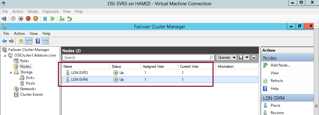
10 – Verify all nodes status now up…
11 – Next, expand Storage, and then click Disks.
In the center pane, right-click the disk that is assigned to Disk Witness in Quorum then click Take Offline…
“** Quorum is the number of elements that must be online for a cluster to continue running. In effect, each element can cast one vote to determine whether the cluster continues to run. Each cluster node is an element that has one vote. In case there is an even number of nodes, then an additional element, which is known as a witness, is
assigned to the cluster. The witness element can be either a disk or a file share. Each voting element contains a copy of the cluster configuration; and the Cluster service works to keep all copies synchronized at all times.”

12 – then click Yes…

13 – Switch to DC1 server and verify that you can still access the \\osi-fs\osi-docs location. By doing this, you
verified that the cluster is still running, even if the witness disk is offline…

14 – Now switch back to SVr3 server, in Failover Cluster Manager, expand Storage, click Disks, right-click the disk that is in Offline status, and then click Bring Online…

15 – Next, right-click Cluster1.Adatum.com, select More Actions, and then click Configure Cluster Quorum Settings…

16 – click Next…

17 – On the Select Quorum Configuration Option interface, click Advanced quorum configuration, and then click Next…

18 – On the Select Voting Configuration interface,Do not make any changes, and then click Next…

19 – On the Select Quorum Witness interface, select Configure a disk witness and then click Next…

20 – On the Configure Storage Witness interface, select Cluster Disk 3, and then click Next…

21 – click Next…

22 – click Finish…
** we have succesfully tested the failover scenarios and next we going to configure CAU

8th : Configure CAU – Cluster-Aware Updating
** Cluster-Aware Updating (CAU) is a technology in Windows Server 2012 that automatically updates cluster nodes with Windows Update hotfix, by keeping the cluster online, and minimizing downtime.
** During an update procedure, CAU transparently takes each cluster node offline, installs the updates and any dependent updates, and then performs a restart if necessary. CAU then brings the node back online, and moves to update the next node in a cluster.
1 – Before we proceed, please make sure that you have install Failover Clustering feature in DC1 Domain Server…
2 – Switch back to SVR3 & SVR4 server, and please verify also that Inbound Rule for Remote Shutdown (RPC-EP-In) & Inbound Rule for Remote Shutdown (TCP-In) rule is enabled…

3 – let’s return to DC1 domain server and open Cluster-Aware Updating console…

4 – In the Cluster-Aware Updating interface, in the Connect to a failover cluster drop-down list box, select OSICLUSTER1, and then click Connect…

5 – In the Cluster Actions pane, click Preview updates for this cluster…

6 – In the OSICluster1-Preview Updates interface, click Generate Update Preview List…

7 – After few minutes, updates will display in the list and then click Close…

8 – still on the DC1 server, now we need to update the failover cluster and configure the self-updating…
** in the Cluster-Aware Updating console, click Apply updates to this cluster…

9 – On the Getting Started interface, click Next…

10 – On the Advanced options interface, review the options for updating, and then click Next…

11 – On the Additional Update Options interface, click Next…

12 – On the Confirmation interface, click Update, and then click Close…

13 – In the Cluster nodes pane, you can review the progress of the updating process…
** Please take note that 1 node of the cluster is in a waiting state, and the other node is restarting after it is updated.
** Wait until the process is finished and both nodes will restarted automatically.

14 – The process is finished when both nodes show Succeeded…

15 – Once the SVR3 restarted, log in as administrator and open Cluster-Aware Updating…
** In the Cluster-Aware Updating box, in the Connect to a failover cluster drop-down list box, select OSICLUSTER1. Click Connect….

16 – Click the Configure cluster self-updating options in the Cluster Actions pane…

17 – On the Getting Started interface, click Next…

18 – On the Add CAU Clustered Role with Self-Updating Enabled interface, click Add the CAU clustered role, with self-updating mode enabled, to this cluster, and then click Next…

19 – On the Specify self-updating schedule page,configure your own schedule and then click Next…

20 – On the Advanced Options interface, click Next…

21 – On the Additional Update Options interface, click Next….

22 – On the Confirmation interface, click Apply…

23 – After the clustered role is added successfully, click Close and we have successfully configured CAU.

That’s all for now.. i know its a long step, but i hope for those who taking MCSA exam code 70-412, you should do a lot of exercises on the Failover Cluster.
Wait for my Failover Clustering with Hyper-V post in next few week… 🙂
Some organizations need to deploy multiple domains or even multiple forests.
Deploying AD DS domain controllers in this scenario is not much more complicated than deploying domain controllers in a single domain environment, but there are some special factors that you need to consider.
In this post this time , i’ll show you how to deploy a complex ADDS environment, what i’m going to cover in my post this time?
1 – Implementing Child Domains in AD DS
2 – Trust configuration
3 – Implementing Forest Trusts
4 – forest trust authentication
For more information on the ADDS, please log in to : http://technet.microsoft.com/en-us/library/hh831484.aspx
Before we start, for this demo purposes, i’ll be using 3 domain server and 1 Member Server so that i can stimulate the child domain process & trust process…
My Domain Server consist of :
1 – TOR-DC1
2 – LON-DC1
3 – TREY-DC1
4 – LON-SVR2 (Member Server)
Lets get started…
1st – Installing Active Directory Domain Services on Child Domain
1 – on the TOR-DC1 domain server, make sure you install Active Directory Domain Services (i skip this step, i pretty sure that most of you know how to complete this step)..
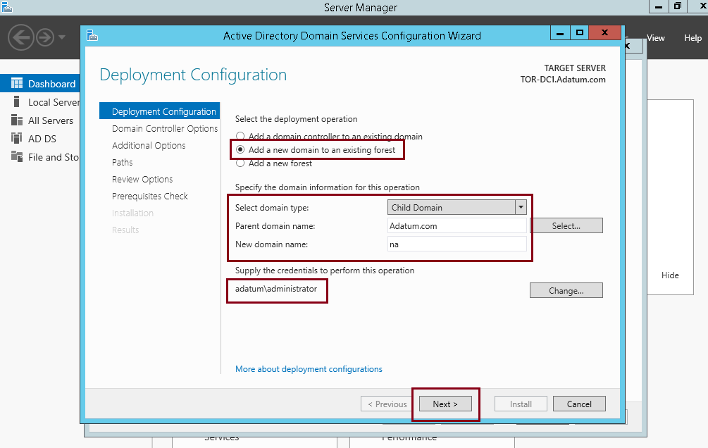
2 – On the the Deployment Configuration interface, click Add a new domain to an existing forest…
** Verify that Select domain type is set to Child Domain, and that Parent domain name is set to Adatum.com.
** In the New domain name text box, type na.
** set credentials to ADATUM\administrator (Current user), and then click Next…
3 – In the Domain Controller Options interface, verify that Domain functional level is set to Windows Server 2012 R2.
** verify that both the Domain Name system (DNS) server and Global Catalog (GC) check boxes are selected.
** Confirm that Site name: is set to Default-First-Site-Name.
** Complete the password and proceed with next…

4 – On the DNS Options interface, click Next…

5 – On the Additional Options interface, click Next…

6 – On the Paths interface, click Next…

7 – On the Review Options interface, click Next…

8 – On the Prerequisites Check interface, confirm that there are no issues, and then click Install…

9 – N0w lets verify the the default trust configuration, once the TOR-DC1 restarted, log in NA\Administrator…
** i do recommend that you check your network connection is connected to adatum.com, if not please right-click Ethernet, and then click Disable. Right-click Ethernet, and then click Enable, then verify that Local Area Connection should now show Adatum.com…

10 – Next, open Active Directory Domains and Trusts…

11 – In the Active Directory Domains and Trusts console, expand Adatum.com, right-click na.adatum.com, and then click Properties…

12 – In the na.adatum.com Properties box, click the Trusts tab, and in the Domain trusted by this domain (outgoing trusts) box, click Adatum.com, and then click Properties…

13 – In the Adatum.com Properties box, click Validate, and then click Yes, validate the incoming trust…

14 – In the User name text box, type administrator, and in the Password text box, type Pa$$w0rd, and then click OK…

15 – When the message The trust has been validated. It is in place and active displays, click OK..
** Click OK twice to close the Adatum.com Properties box.

As at this step, we have successfully implemented child domains in ADDS.
2nd – Implementing Forest Trusts
1 – Switch to LON-DC1 Domain Server, and open DNS…
2 – In the DNS tree pane, expand LON-DC1, right-click Forward Lookup Zones, and then click New Zone…

3 – In the New Zone Wizard interface, click Next…

4 – On the Zone Type interface, click Stub zone, and then click Next…

5 – On the Active Directory Zone Replication Scope interface, click To all DNS servers running on domain controllers in this forest: adatum.com, and then click Next…

6 – In the Zone name: text box, type treyresearch.net, and then click Next…

6 – On the Master DNS Servers inetrface, click <Click here to add an IP Address or DNS Name>, type 172.16.10.10, click on the free space, and then click Next…
** 172.16.10.10 – TREY-DC1

7 – On the Completing the New Zone Wizard interface, click Next, and then click Finish…

8 – Next, right-click the new stub zone treyresearch.net, and then click Transfer from Master and then refresh…
** Confirm that the treyresearch.net stub zone contains records…

9 – Now lets switch to TREY-DC1, open DNS,
** In the tree pane, expand TREY-DC1, select and then right-click Forward Lookup Zones, and then click New Zone.

10 – In the New Zone Wizard interface, click Next…

11 – On the Zone Type interface, click Stub zone, and then click Next…

12 – In the Active Directory Zone Replication Scope interface, click To all DNS servers running on domain controllers in this forest: Treyresearch.net, and then click Next…

13 – In the Zone name: text box, type adatum.com, and then click Next…

14 – On the Master DNS Servers interface, click <Click here to add an IP Address or DNS Name>, type 172.16.0.10, click on the free space, and then click Next…
** 172.16.0.10 – LON-DC01

15 – On the Completing the New Zone Wizard interface, click Next, and then click Finish…

16 – Select and then right-click the new stub zone adatum.com, and then click Transfer from Master…

17 – Right-click adatum.com, and then click Refresh and then confirm that the adatum.com stub zone contains records…

3rd – Next step is to configure a forest trust with authentication…
1 – Switch to LON-DC1, and open Active Directory Domain and Trusts…
2 – In the Active Directory Domains and Trusts management console, right-click Adatum.com, and then click Properties…

3 – In the Adatum.com Properties dialog box, click the Trusts tab, and then click New Trust…

4 – On the New Trust Wizard interface, click Next…

5 – In the Name text box, type treyresearch.net, and then click Next…

6 – On the Trust Type interface, click Forest trust, and then click Next…

7 – On the Direction of Trust interface, click One-way: outgoing, and then click Next…

8 – On the Sides of Trust interface, click Both this domain and the specified domain, and then click Next…

9 – On the User Name and Password interface, type Administrator as the user name and Pa$$w0rd as the password in the appropriate boxes, and then click Next…

10 – On the Outgoing Trust Authentication Level–Local Forest interface, click Selective authentication, and then click Next…

11 – On the Trust Selections Complete interface, click Next…

12 – On the Trust Creation Complete interface, click Next…

13 – On the Confirm Outgoing Trust interface, click Next…

14 – Click Finish…

15 – In the Adatum.com Properties dialog box, click the Trusts tab…
** On the Trusts tab, under Domains trusted by this domain (outgoing trusts), click TreyResearch.net, and then click Properties…

16 – In the treyresearch.net Properties dialog box, click Validate…

17 – Review the message that displays: The trust has been validated. It is in place and active, and then click OK…

18 – Click Yes and close all the interface…

4th – Configure a member server for selective authentication…
1 – On LON-DC1 server, open Active Directory Users and Computers, click View menu, click Advanced Features…

2 – Expand Adatum.com, and then click Computers, right-click LON-SVR2, and then click Properties…

3 – In the LON-SVR2 Properties box, click the Security tab, and then click Add…

4 – On the Select Users, Computers, Service Accounts, or Groups page, click Locations…

5 – Click TreyResearch.net, and then click OK…

6 – In the Enter Network Credentials box, type treyresearch\administrator with the password Pa$$w0rd, and then click OK…
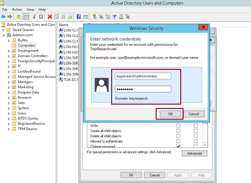
7 – In the Enter the object name to select (examples:) text box, type IT then click OK…

8 – In the LON-SVR2 Properties interface, verify that IT (TreyResearch\IT) is highlighted, select the Allow check box that is in line with Allowed to authenticate, and then click OK…

9 – Now lets switch to LON-SVR2 member server, create a folder in the C:, then Right-click the folder that you just created, point to Share with, and then click Specific People…

10 – In the File Sharing dialog box, type TreyResearch\IT, and then click Add…

11 – Click Read, and then click Read/Write. Click Share… and then click Done….

12 – Sign in to TREY-DC1 as TreyResearch\Alice or any domain user that you have in IT OU…

13 – open Run and type \\LON-SVR2\IT-Technical-Data, and then click OK…

14 – Verify that you have access to that IT-Technical-Data folder that located in LON-SVR2…

finally, we have successfully implemented forest trusts….
FTP (File Transfer Protocol) is a very popular protocol that allows users to upload and download files easily.
Even FTP consider a quite legacy data transfer technology, but it still usable and easy to use by some of Server Administrator.
You can configure FTP server in Windows Server 2012 by installing FTP server role.
In this post, I will show you a very simple step how to install and configure FTP server role in Windows Server 2012 R2.
1st – You need to setup authentication for user in Domain environment before installing FTP roles.
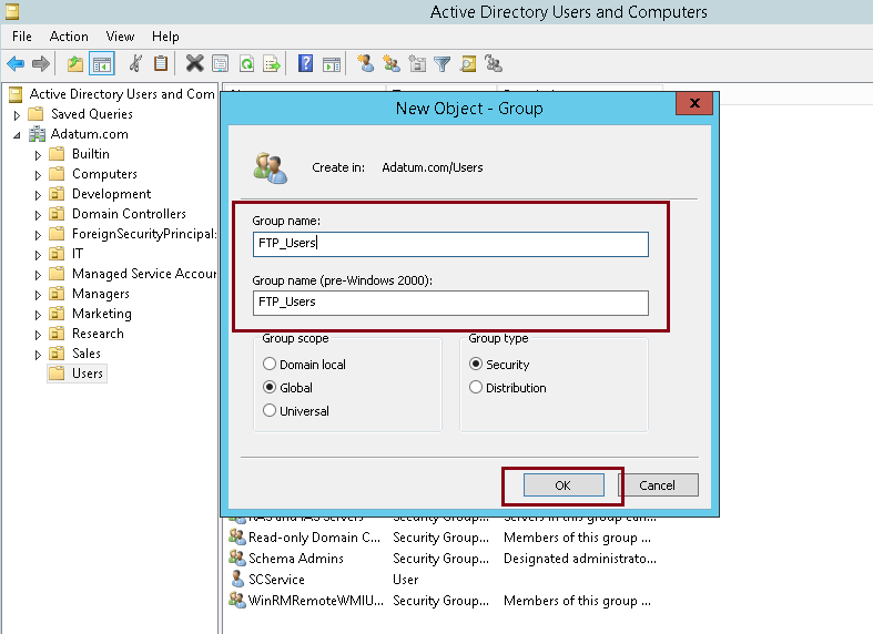
1 – In your Domain Server, open Active Directory Users & Computers, and create FTP_Users group.
2 – In the FTP_Users properties, please add Administrator and any user that need to use / log in to FTP Server…

3 – Now lets switch to Member Server, and create a folder for your FTP access then right click the FTP folder and click Security.
** In the FTP folder properties, under Security click Advanced…
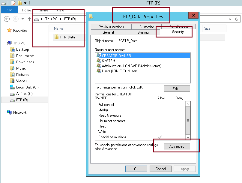
4 – On the Advanced Security Settings for FTP folder, click add…
** what we going to do here is to give access permissions to FTP_Users group…

5 – On the Permission Entry for FTP folder, click Select a principal link, then under Enter the object name to select, type FTP_Users and click OK…
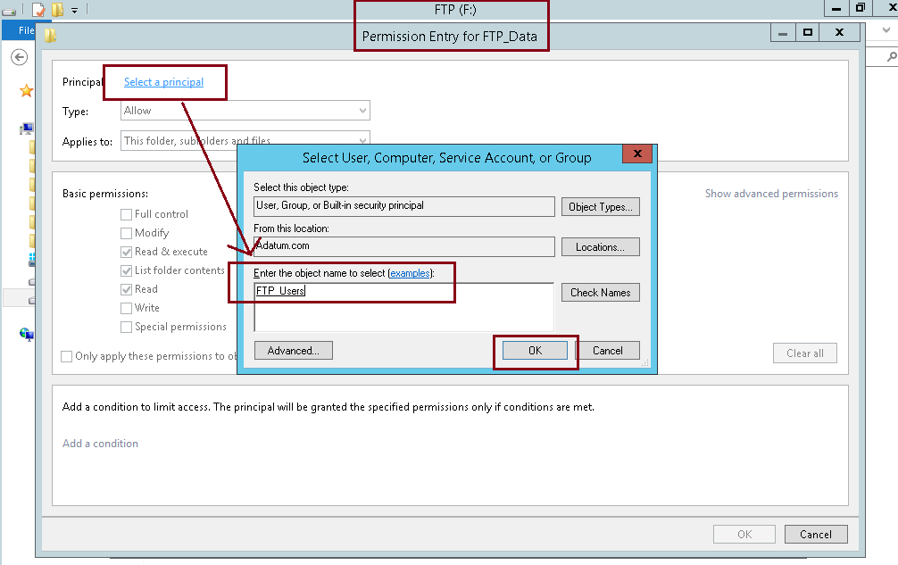
6 – On the Permission Entry for FTP folder, under Basic permissions, click Write and then click OK…

7 – verify that FTP_Users is listed under Advanced Security Setting for FTP folder…

2nd – Installing FTP Role service…
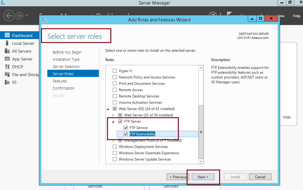
1 – Still in the member server, open Server Manager, click Add roles & features and proceed to server roles and browse for FTP Server (click FTP Service and FTP Extensibility), then click Next…
2 – On the Select features interface, proceed with Next…

3 – On the Confirm installation selections interface, click Install…

4 – Once installation complete, please restart the Server…

5 – Once server restarted, open Server Manager, click Tools and click Internet Information Services (IIS) Manager…

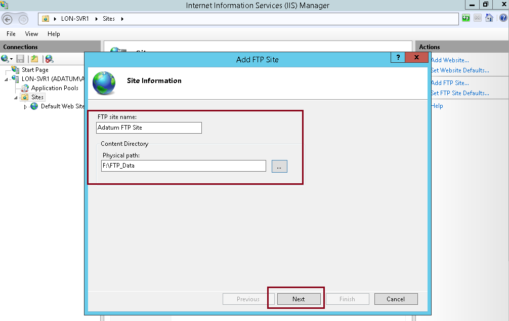
6 – On the IIS console, right click Sites and click Add FTP Site…

7 – On the Add FTP Site interface, in the FTP Site name:, enter your own FTP site name, then in Physical path, browse to FTP folder that you created in the previous step…
8 – Under Add FTP Site interface, verify that the IP Address assigned to All Unassigned with Port 21…
** click No SSL (I’m not going to secure this FTP site with web certificates)… and click Next…

9 – Under Authentication click Basic, under Allow access to:, choose Specified roles or user groups and type FTP_Users, confirm that you click Read & write under Permissions, then click Finish…

10 – Next, open Windows Firewall and click Allow an app or feature through Windows Firewall…

11 – Under Allow apps to communicate through Windows Firewall, browse to FTP Server and verify that and Domain, Private and Public are ticked, and then click OK…

12 – Next, open Windows Firewall with Advanced Security, click Inbound Rules and scroll to FTP (verify that 3 FTP component listed)…

13 – Now, lets switch to client PC (in this demo i use Windows 8.1)…
** in the client PC, open CMD and type telnet 172.16.0.21 21
** 172.16.0.21 –> FTP server IP
** 21 –> FTP port number

14 – on the CMD, it stated 220 Microsoft FTP Service (we have successfully connected to FTP Server)…

15 – Now open web browser, in the address bar type ftp://172.16.0.21 and enter, click view menu and then click Open FTP site in File Explorer…

16 – On the Log On As box, under user name, fill in with any of your FTP_Users, then fill in the password and click Log On…

17 – Once you successfully log in to FTP Server, you can try create any folder…

18 – Lastly, switch back to FTP server and confirm that the folder you created is listed in the FTP server…

Orait, that’s all for now..
Thank you for reading this….
With the development of IPv6 and the bunch of devices that require IP addresses, networks have become so much complex and difficult for us to manage.
Maintaining an updated list of static IP addresses that have been issued has often been a manual task, which can lead to errors. To help organizations manage IP addresses, Windows Server 2012 R2 provides the IP Address Management (IPAM) tool.
IP address management is a difficult task in large networks, because tracking IP address usage is largely a manual operation. Windows Server 2012 introduces IPAM, which is a framework for discovering, auditing, monitoring utilization, and managing the IP address space in a network.
IPAM enables the administration and monitoring of DHCP and DNS, and provides a comprehensive view of where IP addresses are used.
IPAM collects information from domain controllers and Network Policy Servers (NPSs), and then stores that information in the Windows Internal Database.
Benefits of IPAM :
• IPv4 and IPv6 address space planning and allocation.
• IP address space utilization statistics and trend monitoring.
• Static IP inventory management, lifetime management, and DHCP and DNS record creation and deletion.
• Service and zone monitoring of DNS services.
• IP address lease and logon event tracking.
• Role-based access control (RBAC).
• Remote administration support through RSAT.
• Reporting in the IPAM management console.
There are a lot of information about IPAM that you may discover, if you need more thorough information, please log in to : http://technet.microsoft.com/en-us/library/hh831353.aspx
In case you are interested to learn how to implement & configuring IPAM, please make sure that you prepare a complete LAB environment and of course you may setup the whole infrastructure in Hyper-V. Confirm that you have 1 Domain Server and at least 1 member server, in this demo, i will use adatum domain with 1 Domain Controller Server and 2 Member Server, which is SVR1 & SVR2.
There are almost 40 over step just to complete the basic of IPAM implementation & configuration, so please spend some time to read and understand how IPAM working in Windows Server 2012 R2.
Lets get started…
1st – Installing IPAM in Member Server…
1 – Log in to your domain member Server (SVR2), open Server Manager, click add roles & features, proceed to Select features interface, and select the IP Address Management (IPAM) Server check box and proceed with Next…

2 – On the Confirm installation selections interface, click Install…

3 – Close the Installation progress interface when installation is complete…

2nd – Provisioning IPAM through a Group Policy Object (GPO)…
1 – In the Member server, on the Server Manager, click IPAM…

2 – In the IPAM Overview interface, click Connect to IPAM server…

3 – On the Connect to an IPAM Server interface, click LON-SVR2.Adatum.com, and then click OK…

4 – Next, click Provision the IPAM server…

5 – In the Provision IPAM Wizard interface, on the Before you begin page, click Next…

6 – On the Configure database interface, click Next…

7 – On the Select provisioning method interface, ensure that the Group Policy Based is selected then in the GPO name prefix box, type IPAM, and then click Next…

8 – On the Confirm the Settings interface, click Apply.
** Provisioning will take a few minutes to complete…

9 – Click Close once provisioning is complete…

3rd – Configure IP Management Server Discovery…
1 – On the IPAM Overview interface, click Configure server discovery…

2 – In the Configure Server Discovery settings box, click Add (verify that you add the correct domain)…

3 – On the Configure Server Discovery box, confirm that Domain Controller, DHCP Server and DNS Server is selected and then click OK…

4 – In the IPAM Overview interface, click Start server discovery.
** Discovery may take around 5 to 10 minutes to run…

5 – After few minutes, the yellow bar will indicate that the discovery is completed…

4th – Configure managed servers…
1 – In the IPAM Overview interface, click Select or add servers to manage and verify IPAM access.

2 – Notice that the IPAM Access Status is blocked…
** This also indicate that IPAM server has not yet been granted permission to manage the domain server via Group Policy

3 – I will use Windows PowerShell to provisioning the IPAM GPO…

4 – In the Windows PowerShell, type :
Invoke-IpamGpoProvisioning –Domain Adatum.com –GpoPrefixName IPAM –IpamServerFqdn LON-SVR2.adatum.com –DelegatedGpoUser Administrator
** When you are prompted to confirm the action, type Y, and then press Enter.
** The command will take a few minutes to complete…

5 – Next, in the SERVER INVENTORY>IPv4 pane, right-click LON-DC1, and then click Edit Server…

6 – In the Add or Edit Server box, set the Manageability status to Managed, and then click OK…

7 – Please switch to Domain Server and run gpudate /boot /force command to update the IPAM GPO…
8 – Next, in the IPAM console, right-click LON-DC1, and then click Refresh Server Access Status…
** It may take up to 10 minutes for the status to change…

9 – Refresh tasks as needed until a green check mark displays next to LON-DC1 and the IPAM Access Status shows Unblocked for the server…
10 – Next, right-click LON-DC1 and then click Retrieve ALL Server Data.
This action also will take a few minutes to complete….

5th – Configure and verify a new DHCP scope with IPAM…
1 – in the IPAM navigation interface, under MONITOR AND MANAGE, click DNS and DHCP Servers.
** then right-click the instance of LON-DC1.Adatum.com that contains the DHCP server role, and then click Create DHCP Scope.

2 – In the Create DHCP Scope box, in the Scope Name box, type Branch Scope…
** In the Start IP address box, type 10.0.0.50
** In the End IP address box, type 10.0.0.100
** subnet mask is 255.0.0.0

3 – In the Create scope pane, click Options…
** On the DHCP Scope Options interface, click New…
** In the Configure options interface, in the Option select 003 Router…
** Under Values, in the IP Address box, type 10.0.0.1, click Add Configuration, and then click OK…

4 – Verify the configuration, then click OK…

5 – In the navigation interface, click DHCP Scopes, then right-click Branch Scope, and then click Configure DHCP Failover…

6 – In the Configure DHCP Failover Relationship interface, for the Partner server field, click the click lon-svr1.adatum.com…
** In the Relationship Name field, type AdatumDHCPFailover…
** In the Enable Message Authentication Secret field, type Pa$$w0rd
** In the Maximum Client Lead Time field, set the minutes to 10
** Ensure the Mode field is set to Load balance

** Verify that the Load Balance Percentage is set to 50%
** Select the Enable state switchover check box. Leave the default value of 60 minutes and then click OK…

7 – switch to Domain Server, and open DHCP console…
** expand lon-dc1.adatum.com, expand IPv4, and confirm that Branch Scope exists…

6th – Configure IP address blocks, record IP addresses, and create DHCP reservations and DNS records
1 – Still in IPAM Server, click IP Address Blocks, in the right pane, click the Tasks drop-down arrow, and then click Add IP Address Block…

2 – In the Add or Edit IPv4 Address Block box, provide the following values, and then click OK: (please refer to picture)

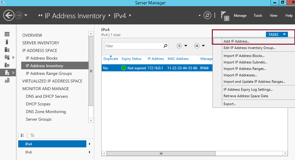
3 – Next, click IP Address Inventory, in the right pane, click the Tasks drop-down arrow, and then click Add IP Address…

4 – In the Add IP Address box, under Basic Configurations, provide the following values :

5 – Click again the Tasks drop-down arrow, and then click Add IP Address…
6 – In the Add IP Address box, under Basic Configuration, provide the following values : (Please refer to the picture)

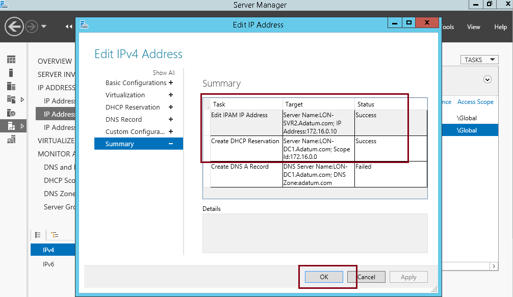
7 – In the Add IPv4 Address pane, click DHCP Reservation, and then enter the following values : (Please refer to the picture)…

8 – In the Add IPv4 Address pane, click DNS Record, enter the following values : (Please refer to the picture)…

9 – On the Summary interface, verify that the task is complete without failed…
10 – Switch to Domain Server and open DHCP console, expand IPv4, expand Scope (172.16.0.0) Adatum, and then
click Reservations.
** Verify that the reservation for 172.16.0.10 is displays.

11 – Lastly, open the DNS console, expand Forward Lookup Zones, and then click Adatum.com.
** Verify that a host record displays for Webserver

Wow, what a long step.. we done for now, and if as at this step, we manage to installed IPAM and configured IPAM with IPAM related GPOs, IP management server discovery, managed servers, a new DHCP scope, IP address blocks, IP addresses, DHCP reservations, and DNS records.
As we all know, DNS is one of the most critical network services for any network, because there are many applications and services such as ADDS, rely on DNS to resolve resource names to IP addresses.
Without DNS, user authentications fail, and network-based resources and applications might become inaccessible.
For these reasons in mind, you need to manage and protect DNS.
Since DNS is a critical network service, as a Server Administrator you must protect it as much as possible.
A number of options are available for protecting the DNS server, including :
• DNS cache locking
• DNS socket pool
• DNSSEC
Before we start the step by step to implement the DNS Security, lets go through a theory behind this technology.
DNS Cache Locking
Cache locking is a Windows Server 2012 R2 security feature that allows you to control when information in the DNS cache can be overwritten. When a recursive DNS server responds to a query, it caches the results so that it can respond quickly if it receives another query requesting the same information. The period of time the DNS server keeps information in its cache is determined by the Time to Live (TTL) value for a resource record.
DNS Socket Pool
The DNS socket pool enables a DNS server to use source port randomization when it issues DNS queries. When the DNS service starts, the server chooses a source port from a pool of sockets that are available for issuing queries. Instead of using a predicable source port, the DNS server uses a random port number that it selects from the DNS socket pool. The DNS socket pool makes cache-tampering attacks more difficult because a malicious user must correctly guess both the source port of a DNS query and a random transaction ID to successfully run the attack. The DNS socket pool is enabled by default in Windows Server 2012 R2.
DNSSEC
DNSSEC enables a DNS zone and all records in the zone to be signed cryptographically so that client computers can validate the DNS response. DNS is often subject to various attacks, such as spoofing and cache-tampering. DNSSEC helps protect against these threats and provides a more secure DNS infrastructure.
For more information, please log in to : http://technet.microsoft.com/en-us/library/cc731367.aspx
So now, lets go through a simple step how you as Server Administrator can implement DNS Security.
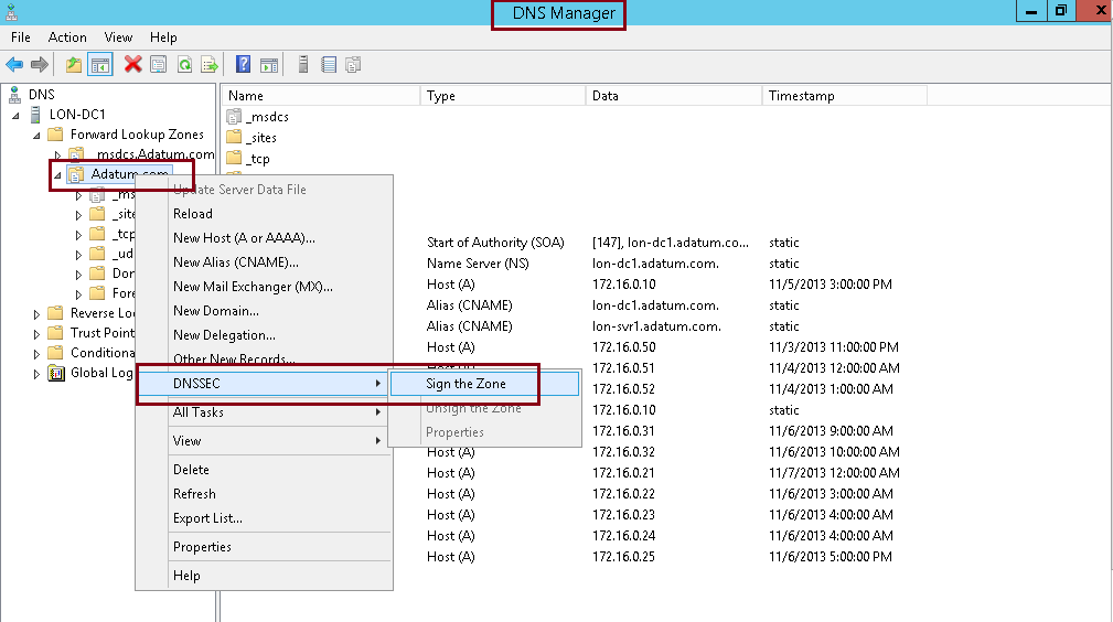
1st – Step to configure DNSSEC.
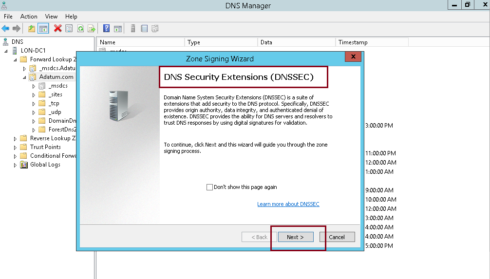
1 – Open Server Manager, click Tools and open DNS Manager, in the DNS Manager, browse to your Domain name, then right click domain name, click DNSSEC and then click Sign the Zone…
2 – In the Zone Signing Wizard interface, click Next…
3 – On the Signing options interface, click Customize zone signing parameters, and then click Next…

4 – On the Key Master interface, ensure that “The DNS server LON-DC1 is selected as the Key Master“, and then click Next…

5 – On the Key Signing Key (KSK) interface, click Next…

6 – On the Key Signing Key (KSK) interface, click Add…

7 – On the New Key Signing Key (KSK) interface, click OK…
** please spend some time to go through about key properties on the New Key Signing Key (KSK) interface.

8 – On the Key Signing Key (KSK) interface, click Next…

9 – On the Zone Signing Key (ZSK) interface, click Next…

10 – On the Zone Signing Key (ZSK) interface, click Add…

11 – On the New Zone Signing Key (ZSK) interface, click OK…

12 – On the Zone Signing Key (ZSK) interface, click Next…

13 – On the Next Secure (NSEC) interface, click Next…
** NSEC is when the DNS response has no data to provide to the client, this record authenticates that the host does not exist…

14 – On the Trust Anchors (TAs) interface, check the Enable the distribution of trust anchors for this zone check box, and then click Next.
** A trust anchor is an authoritative entity that is represented by a public key. The TrustAnchors zone stores
preconfigured public keys that are associated with a specific zone.

15 – On the Signing and Polling Parameters interface, click Next…

16 – On the DNS Security Extensions (DNSSEC) interface, click Next, and then click Finish…


17 – In the DNS console, expand Trust Points, expand com, and then click your domain name.
Ensure that the DNSKEY resource records display, and that their status is valid…

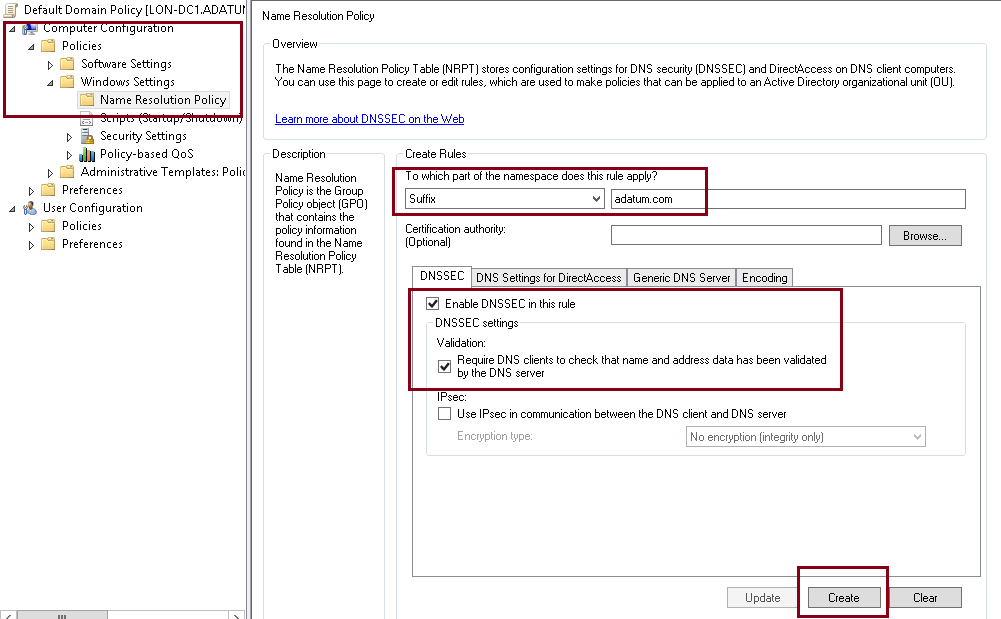
18 – Next, open Group Policy Management, expand Forest: Adatum.com, expand Domains, expand Adatum.com, right-click Default Domain Policy, and then click Edit…

19 – In the Group Policy Management Editor interface, under Computer Configuration, expand Policies, expand Windows Settings, and then click Name Resolution Policy…
** In the right pane, under Create Rules, in the Suffix box, type Adatum.com to apply the rule to the suffix of the namespace.
** Select both the Enable DNSSEC in this rule check box and the Require DNS clients to check that the name and address data has been validated by the DNS server check box, and then click Create.
2nd – Configure the DNS Socket Pool
1 – In domain Server, open Windows PowerShell and type : Get-DNSServer
** This command displays the current size of the DNS socket pool (on the fourth line in the ServerSetting section). Note that the current size is 2,500.
*** Please take note that the default DNS socket pool size is 2,500. When you configure the DNS socket pool, you can choose a size value from 0 to 10,000. The larger the value, the greater the protection you will have against DNS spoofing attacks.

2 – Now lets change the socket pool size to 3,000…
type : dnscmd /config /socketpoolsize 3000

3 – Restart your DNS Server for the changes to take effect…
** confirm that the new socket pool size now is 3000

3rd – Configure the DNS Cache Locking
1 – In Windows PowerShell, type Get-Dnsserver
** This command will displays the current percentage value of the DNS cache lock.
** Note that the current value is 100 percent.

2 – type Set-DnsServerCache –LockingPercent 70
** This changes the cache lock value to 70 percent
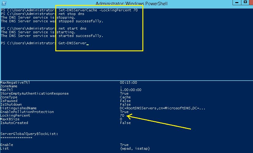
*** Please take note that you configure cache locking as a percentage value.
For example, if the cache locking value is set to 50, then the DNS server will not overwrite a cached entry for half of the duration of the TTL.
So By default, the cache locking percentage value is 100.
This means that cached entries will not be overwritten for the entire duration of the TTL.
So, as a best practice, you should set your cache locking settings to at least 90%.
OK folk, that’s all for now, i will continue blogging later on the how to configure a GlobalNames zone in DNS.